
Electronic device with self direction detection function and control method thereof

An electronic device and azimuth detection technology, applied in telephone communication, electrical components, sub-office equipment, etc.

Inactive Publication Date: 2010-06-16
E-TEN
View PDF0 Cites 1 Cited by
  • Summary
  • Abstract
  • Description
  • Claims
  • Application Information

AI Technical Summary

Problems solved by technology

[0003] However, although the electronic device is equipped with screens or image capture devices on both sides, when the screen on one side is in use, the user may change hands due to hand fatigue, or temporarily turn the electronic device to hold something. Put it on the table, and when you pick it up later, you will find that the other side is facing the user

Method used


Image

  • Electronic device with self direction detection function and control method thereof
  • Electronic device with self direction detection function and control method thereof
  • Electronic device with self direction detection function and control method thereof

Examples


no. 1 example

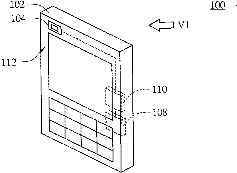
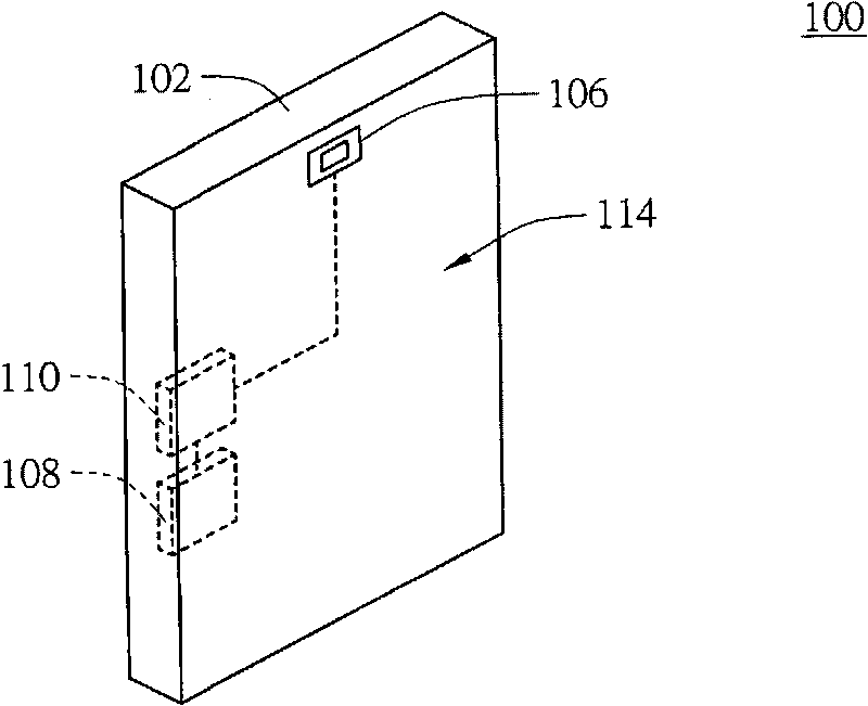
[0032] Please also refer to figure 1 and figure 2 , figure 1 It shows an electronic device with self-orientation detection function according to the first embodiment of the present invention, figure 2 draw figure 1 A view of the electronic device along direction V1. The electronic device 100 includes a body 102 , a first operating unit such as a first image capturing unit 104 , a second operating unit such as a second image capturing unit 106 , an orientation detector 108 and a processing unit 110 . The first image capture unit 104 and the second image capture unit 106 are, for example, photographic devices or camera lenses. The first image capture unit 104 and the second image capture unit 106 in this embodiment are all described using the photographic device as an example. .

[0033] The body 102 has a first surface 112 and a second surface 114 , the first surface 112 is opposite to the second surface 114 . The first image capturing unit 104 is located on the first s...

no. 2 example

[0045] Please also refer to Figure 4 and Figure 5 , Figure 4 It shows an electronic device with self-orientation detection function according to the second embodiment of the present invention, Figure 5 draw Figure 4 A view of the electronic device along the direction V2. The electronic device 200 includes a body 202, a first image capture unit, such as a photographic lens 204 or a photographic lens, a first display unit, such as a first display screen 206, a second display unit, such as a second display screen 208, an orientation A detector 210 and a processing unit 212 . The first image capture unit in this embodiment is described by taking the photographing lens 204 as an example.

[0046] The body 202 has a first surface 214 and a second surface 216 , the first surface 214 is opposite to the second surface 216 . The camera lens 204 and the second display screen 208 are located on the first surface 214 , and the first display screen 206 is located on the second su...


PUM


Abstract

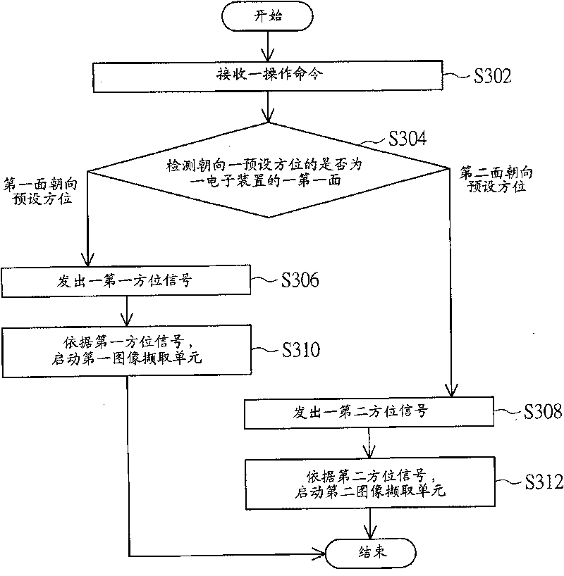
The invention discloses an electronic device with a self direction detection function and a control method thereof. The electronic device comprises a machine body, a first operation unit and a second operation unit, wherein the machine body is provided with a first face and a second face opposite to the first face; the first operation unit is positioned on the first face; and the second operation unit is positioned on the second face. The control method comprises the following steps that: the electronic device receives an operation command; and then the electronic device determines which one of the first face and the second face is towards a preset direction; if the first face is towards the preset direction, the electronic device transmits a first direction signal and starts the first operation unit according to the first direction signal; and if the second face is towards the preset direction, the electronic device transmits a second direction signal and starts the second operation unit according to the second direction signal.

Description

technical field [0001] The present invention relates to an electronic device and its control method, and in particular to an electronic device with self-direction detection function and its control method. Background technique [0002] With the rapid development of mobile communication, various electronic communication devices have sprung up on the market. The functions of the communication device are becoming more and more diversified, for example, image capture devices or screens are installed on both sides of the communication device. The mobile communication devices most commonly used by modern people are, for example, mobile phones or personal digital assistants (Personal Digital Assistant, PDA). Especially mobile phones, which can communicate with others anytime and anywhere, and have a thin and light volume, have gradually become an indispensable part of modern people's life. [0003] However, although the electronic device is equipped with screens or image capture ...

Claims


Application Information

Patent Timeline
IPC IPC(8): H04W88/02H04M1/725H04M1/72454
Inventor 庄孟杰
Owner E-TEN
Learn More