Electric coupler

A technology of electrical connectors and clamping parts, which is applied in the direction of connections, circuits, parts of connection devices, etc., can solve the problems of electrical failure, easy detachment, inconvenience, etc., and achieve the effect of preventing electrical connection failures

Active Publication Date: 2012-05-30
AU OPTRONICS CORP
View PDF0 Cites 0 Cited by
  • Summary
  • Abstract
  • Description
  • Claims
  • Application Information

AI Technical Summary

Problems solved by technology

The conventional electrical connector 100 at least includes an insulating body 110, a plurality of terminals 120 and a cover 130, the terminals 120 are plugged into the insulating body 110, and the cover 130 is combined with the insulating body 110, the cover body 130 is provided with a recessed space S in the middle, so that the two positioning blocks 31 on both sides of a cable 30 can be accommodated in the recessed space S to assemble the electrical connector 100 and the cable 30, however, the cable 30 and the electrical connector 100 are accommodated in the recessed space S only by the positioning blocks 31 of the cable 30. If the cover 130 is opened and closed multiple times or is hit by an external force, The cable 30 is easily detached from the electrical connector 100, resulting in electrical failure
[0003] It can be seen that the above-mentioned existing electrical connector obviously still has inconvenience and defects in structure and use, and needs to be further improved urgently
In order to solve the above-mentioned problems, the relevant manufacturers have tried their best to find a solution, but for a long time no suitable design has been developed, and the general product has no suitable structure to solve the above-mentioned problems. This is obviously the relevant industry. Urgent problem

Method used


Image

  • Electric coupler
  • Electric coupler
  • Electric coupler

Examples


Embodiment Construction

[0050] In order to further explain the technical means and effects of the present invention to achieve the intended purpose of the invention, the specific implementation, structure, characteristics and effects of the electrical connector proposed according to the present invention will be described below in conjunction with the accompanying drawings and preferred embodiments. Detailed description.

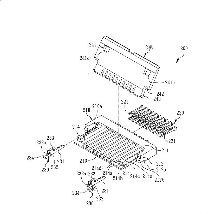
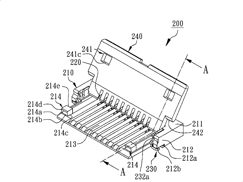
[0051] see figure 2 , image 3 and Figure 4 As shown, they are respectively an exploded perspective view, a perspective view and a perspective view of a specific embodiment of the electrical connector of the present invention. image 3 Schematic cross-sectional view of the A-A direction. A specific embodiment of the present invention is an electrical connector 200 , which includes an insulating body 210 , a plurality of terminals 220 , a pair of fasteners 230 and a cover 240 .

[0052] The above-mentioned insulating body 210 has a body portion 211, a pair of protective bars 2...


PUM


Abstract

The invention relates to an electric coupler, mainly comprising an insulating body, a plurality of terminals and a cover. The insulating body comprises a body part and two first clamping parts. Each first clamping part comprises a first convex part and a first concave part. The terminals are inserted in the body part. The cover is arranged on the insulating body and comprises two second clamping parts. Each second clamping part comprises a second concave part and a second convex part. The first convex part of each first clamping part is clamped on the second concave part of each second clamping part and is limited by the second convex part. The second convex part of each second clamping part is clamped on the first concave part of each first clamping part and is limited by the first convex part. The electric coupler can ensure the arranging wires to be stably bonded on the insulating body to prevent electric connection failure.

Description

technical field [0001] The invention relates to an electrical connector, in particular to an electrical connector with a cover. Background technique [0002] see figure 1 As shown, it is a perspective view of a conventional electric connector inserted with a row of wires. The conventional electrical connector 100 at least includes an insulating body 110, a plurality of terminals 120 and a cover 130, the terminals 120 are plugged into the insulating body 110, and the cover 130 is combined with the insulating body 110, the cover body 130 is provided with a recessed space S in the middle, so that the two positioning blocks 31 on both sides of a cable 30 can be accommodated in the recessed space S to assemble the electrical connector 100 and the cable 30, however, the cable 30 and the electrical connector 100 are accommodated in the recessed space S only by the positioning blocks 31 of the cable 30. If the cover 130 is opened and closed multiple times or is hit by an external ...

Claims


Application Information

Patent Timeline
Patent Type & Authority Patents(China)
IPC IPC(8): H01R12/71H01R13/629H01R13/639H01R13/502
Inventor 王秋文
Owner AU OPTRONICS CORP
Why Eureka
Try Eureka