Fan and control circuit thereof

A control circuit and circuit technology, applied in pump control, control system, motor control, etc., can solve problems such as reduction, damage performance of heating electronic components, temperature rise of heating electronic components, etc., to reduce noise and weaken the superposition of harmonics Effect

Inactive Publication Date: 2010-06-23
FURUI PRECISE COMPONENT (KUNSHAN) CO LTD +1
View PDF0 Cites 2 Cited by
  • Summary
  • Abstract
  • Description
  • Claims
  • Application Information

AI Technical Summary

Problems solved by technology

[0002] With the rapid development of the electronic information industry, the high-speed, high-frequency and integration of heat-generating electronic components such as central processing units will cause a sharp increase in heat generation. If the heat is not removed in time, the temperature of the heat-generating electronic components will rise, which will lead Damage to heat-generating electronic components and degradation of their performance

Method used


Image

  • Fan and control circuit thereof
  • Fan and control circuit thereof
  • Fan and control circuit thereof

Examples


Embodiment Construction

[0010] The present invention will be further described below in conjunction with the embodiments with reference to the accompanying drawings.

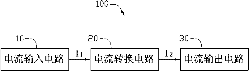
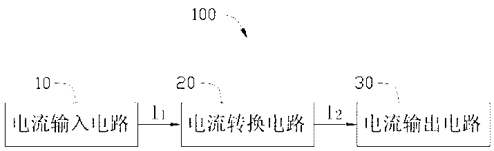
[0011] Please refer to figure 1 , is a functional block diagram of a fan control circuit 100 in a preferred embodiment of the present invention, the control circuit 100 includes a current input circuit 10 , a current conversion circuit 20 and a current output circuit 30 electrically connected in sequence.

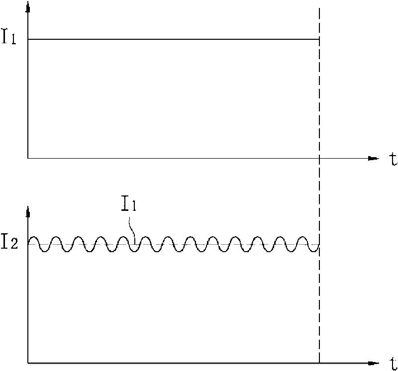
[0012] The current input circuit 10 inputs a constant current I to the current conversion circuit 20 1 . The current conversion circuit 20 converts the input current I 1 Converted to magnitude with this current I 1 Is the floating current I that fluctuates slightly up and down in real time and in the same direction as the reference 2 , and this float current I 2 Output to the current output circuit 30, the current output circuit 30 will float the current I 2 Input to the motor (not shown in the figure) of the fan, so that the ...


PUM


Abstract

The invention relates to a fan, comprising a control circuit, wherein the control circuit is composed of a current input circuit, a current switching circuit and a current output circuit; the current input circuit inputs constant input current to the current switching circuit; the current switching circuit switches the input current into floating current, and the floating current takes the input current as a size reference and can slightly float up and down in real time; the floating current is output to the current output circuit from the current switching circuit; and the current output circuit outputs the floating current to the motor of the fan to lead the rotation speed of the fan to be in a floating state, thus reducing superposition of weak harmonics and lowering noise of the fan.

Description

technical field [0001] The invention relates to a fan, in particular to a fan for cooling heat-generating electronic components and a control circuit thereof. Background technique [0002] With the rapid development of the electronic information industry, the high-speed, high-frequency and integration of heat-generating electronic components such as central processing units will cause a sharp increase in heat generation. If the heat is not removed in time, the temperature of the heat-generating electronic components will rise, which will lead Damage to heat-generating electronic components and degradation of their performance. Therefore, it is necessary to dissipate heat from the heat-generating electronic components. In order to efficiently take away the heat generated by the heating electronic components in a limited space, the industry usually installs a heat dissipation device on the heating electronic components. [0003] The heat dissipation device includes a radiato...

Claims


Application Information

Patent Timeline
Patent Type & Authority Applications(China)
IPC IPC(8): H02P29/00
CPCF04D27/004Y02B30/70
Inventor 黄清白林恒生陈荣安郭伯轩
Owner FURUI PRECISE COMPONENT (KUNSHAN) CO LTD
Why Eureka
Try Eureka