Dust seal structure of internal mixer
A mixer, closed technology, applied in the direction of mixers, engine seals, mixers with rotating stirring devices, etc.
- Summary
- Abstract
- Description
- Claims
- Application Information
AI Technical Summary
Problems solved by technology
Method used
Image
Examples
Embodiment 1
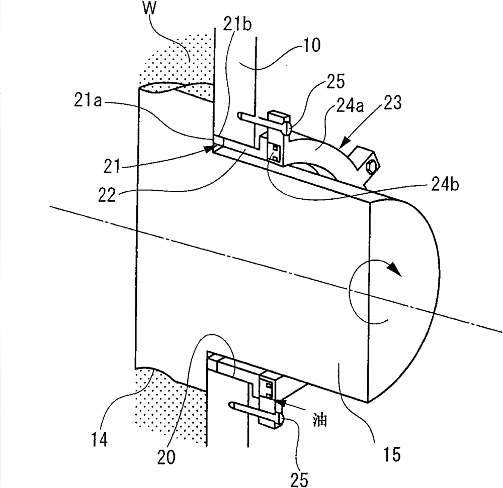
[0042] figure 1 is a perspective sectional view showing the dust sealing structure of Embodiment 1 of the present invention. Figure 10 It is a front sectional view of the basic part of the internal mixer.
[0043] Such as Figure 10 As shown, the housing 10 of the internal mixer, the movable weight 11 and the lifting door 12 form a mixing chamber 13 with a glasses-shaped cross-section.
[0044] The two rotors 14 are disposed parallel to each other in the mixing chamber 13, and are rotated in different directions from each other by driving means (not shown motor, power transmission gear, etc.) installed at the ends of the rotation shafts 15 of the two rotors. A blade portion 16 partially protruding in the radial direction is formed in the rotor 14, and an inner wall of the mixing chamber 13 has a curved surface corresponding to a locus of the blade portion 16 when rotating.
[0045] In this mixer, when the movable weight 11 capable of ascending and descending is raised, ra...
Embodiment 2
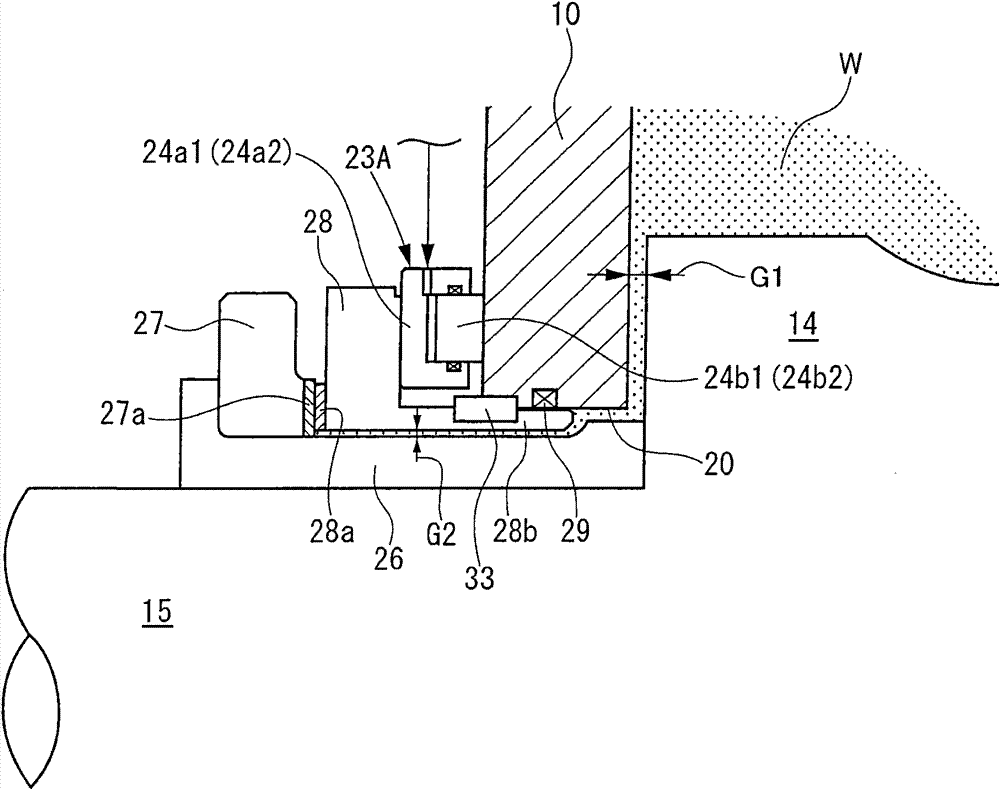
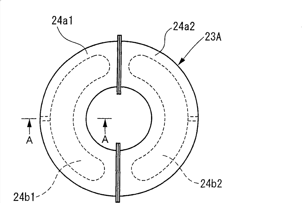
[0052] figure 2 It is a sectional view showing the dust sealing structure of Embodiment 2 of the present invention. image 3 is the front view of the cylinder. Figure 4A is along image 3 Cross-sectional view of midline A-A. Figure 4B is along image 3 A cross-sectional view taken along the center line A-A, where the sealing member for the piston part has been changed. Figure 5 is the deformed front view of the cylinder.
[0053] The dust sealing structure of Embodiment 1 equipped with an annular rotary sealing member 27 is fixedly arranged on the rotating shaft 15 through the sleeve 26, and has a sealing surface 27a on the side opposite to the end surface of the rotor 14, and is connected to the annular cylinder 23A and is pressed in the direction of the shaft end of the rotating shaft 15. The annular fixed sealing member 28 has a sealing surface 28a in contact with the sealing surface 27a of the rotating sealing member 27 and has a tubular shape that is in sliding con...
Embodiment 3
[0063] Image 6 It is a sectional view showing the dust sealing structure of Embodiment 3 of the present invention. Figure 7 is a front sectional view of the cylinder in this embodiment. Figure 8 yes Figure 7 Sectional view of line B-B. Figure 9 It is an explanatory diagram of the piston part.
[0064] In this embodiment, the cylinder 23A including the hydraulic cylinder of Embodiment 2 is replaced by an air suspension type cylinder 23B using a rubber tube 30 or the like, the head portions 24a1, 24a2 are fixed to the outer wall surface of the casing 10 by a plurality of guides 32, and The piston parts 24b1 , 24b2 of the channel part are connected to a fixed sealing member 28 . Since other features are the same as those in Embodiment 2, repeated descriptions are omitted.
[0065] In addition to the same actions and effects as in Embodiment 2, according to the present embodiment, the effects of preventing contaminants (foreign substances in lubricating oil) from enterin...
PUM
 Abstract
Description
Claims
Application Information
 - R&D
- Intellectual Property
- Life Sciences
- Materials
- Tech Scout
- Unparalleled Data Quality
- Higher Quality Content
- 60% Fewer Hallucinations
Browse by: Latest US Patents, China's latest patents, Technical Efficacy Thesaurus, Application Domain, Technology Topic, Popular Technical Reports.
© 2025 PatSnap. All rights reserved.Legal|Privacy policy|Modern Slavery Act Transparency Statement|Sitemap|About US| Contact US: help@patsnap.com


