
Built-in anchor head embedded-type anchoring pile

An embedded and anchor head technology, applied in the field of foundation piles, can solve the problems of increasing the difficulty of drilling, limiting the number of anchor cables, increasing the total length of anchor cables, etc., to save concrete materials, control horizontal deformation, and reduce embedded depth Effect

Active Publication Date: 2011-05-25
CHINA RAILWAY DESIGN GRP CO LTD
View PDF0 Cites 0 Cited by
  • Summary
  • Abstract
  • Description
  • Claims
  • Application Information

AI Technical Summary

Problems solved by technology

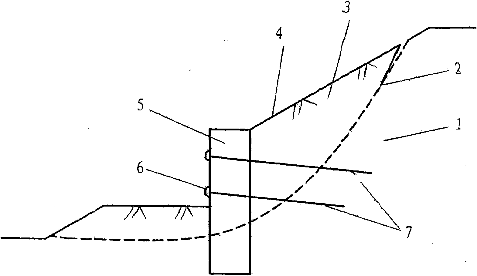
[0007] but, figure 2 In the anti-sliding retaining structure of the anchor-stayed pile shown, the anchor head 6 is set on the front side of the anti-slide pile 5. In order to arrange the anchor head 6 and the anchor cable 7, it is necessary to carry out the soil in front of the pile that can provide a certain amount of anti-sliding force in front of the pile. Partial excavation will affect the overall stability of the landslide treatment project
[0008] At the same time, in order to reduce the excavation of the soil in front of the pile, the anchor heads 6 can only be concentrated near the top of the anchor pile, which affects the distribution of the bending internal force of the anchor pile, and also greatly restricts the number of anchor cables, reducing the skid resistance
Moreover, the anchor head 6 is located near the top of the pile, which increases the total length of the anchor cable, and the long-term prestress loss is relatively large. Due to the relatively long borehole, the difficulty of drilling construction is also increased.

Method used


Image

  • Built-in anchor head embedded-type anchoring pile
  • Built-in anchor head embedded-type anchoring pile
  • Built-in anchor head embedded-type anchoring pile

Examples


Embodiment Construction

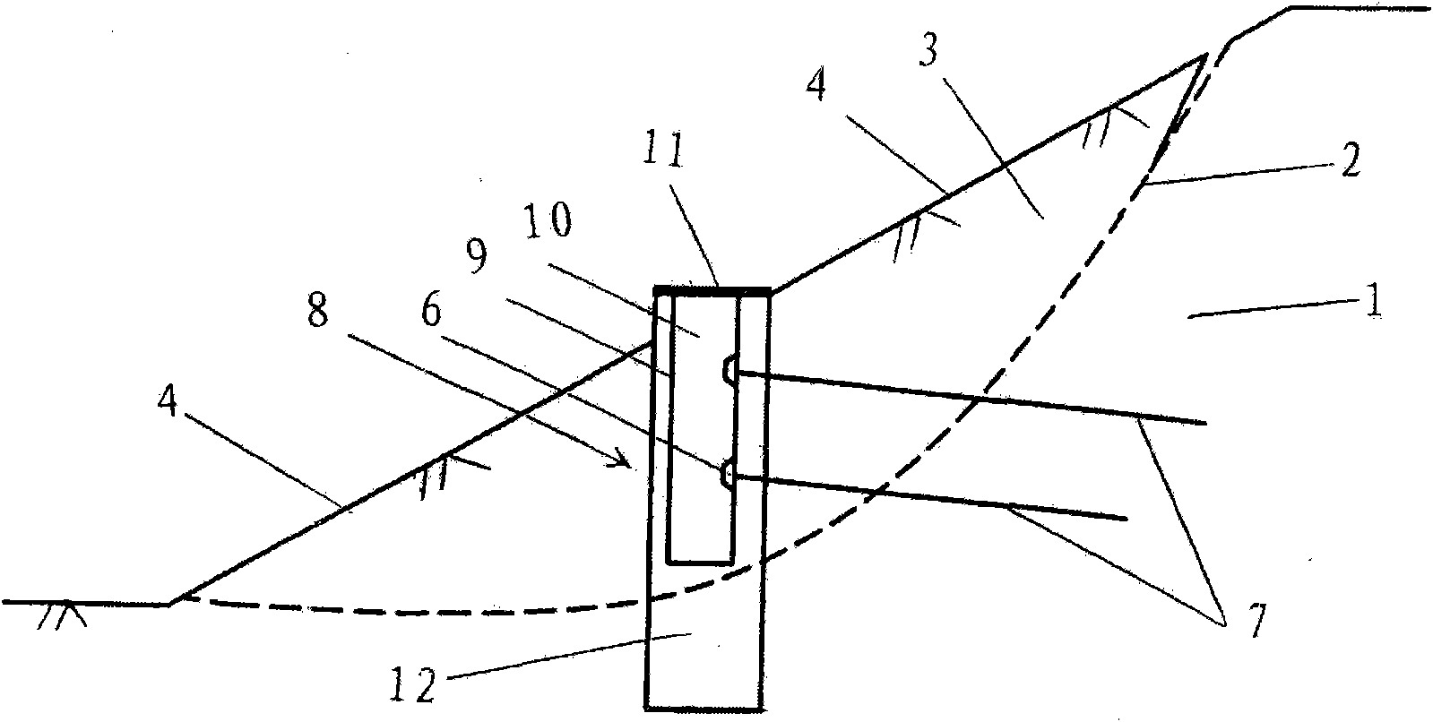
[0040] The specific structure and setting method of the embedded anchor pile with built-in anchor head involved in the present invention will be further described in conjunction with the accompanying drawings. image 3 Shows the state and basic structure of embedded anchor piles embedded in landslides with built-in anchor heads, Figure 4 Showing the cross-sectional structure of the hollow cavity of a buried anchor pile with a built-in anchor head.

[0041] As shown in the figure, the embedded anchor pile with built-in anchor head of the present invention includes a hollow anti-slide pile 8 , an anchor head 6 , an anchor cable 7 and a cover plate 11 . The hollow anti-slide pile 8 is a reinforced concrete pile with a rectangular pile section, and the two sides of the rectangular pile section are the pile section length L and the pile section width W respectively. The upper part of the hollow anti-slide pile 8 is a hollow body 9 forming a hollow cavity 10 inside, and the lower ...


PUM


Abstract

The invention relates to an inbuilt anchor head embedded-type anchoring pile comprising a hollow anti-slide pile, an anchor head, an anchor cable and a cover plate, wherein the hollow anti-slide pile is a reinforced concrete pile of which the section is a rectangle, the upper part is a hollow body, and the lower part is a solid body; the anchor head is fixed on the inner side of the hollow rear wall of the hollow body, an anchor cable connected with the anchor head passes through the hollow rear wall to be fixed in a stable stratum on the rear side of the hollow anti-slide pile, the anchoragedevice of the anchor head locks one end of the anchor cable passing through the hollow rear wall on the inner side of the hollow rear wall, a steel base plate is arranged between the anchorage deviceand the hollow rear wall, and the outer sides of the anchorage device and the steel base plate are sealed by concrete; the cover plate is a reinforced concrete rectangular plate and is covered on theupper mouth of the hollow body of the hollow anti-slide pile to seal the top of the pile. The invention relates to the arrangement method of the inbuilt anchor head embedded-type anchoring pile, comprising: digging a pile hole, pouring concrete, drilling anchor holes, installing the anchor cable and the anchor head, and sealing the pile top. The anchoring pile of the invention has wide application prospect for treating large soil or rock-soil landslide treatment engineering.

Description

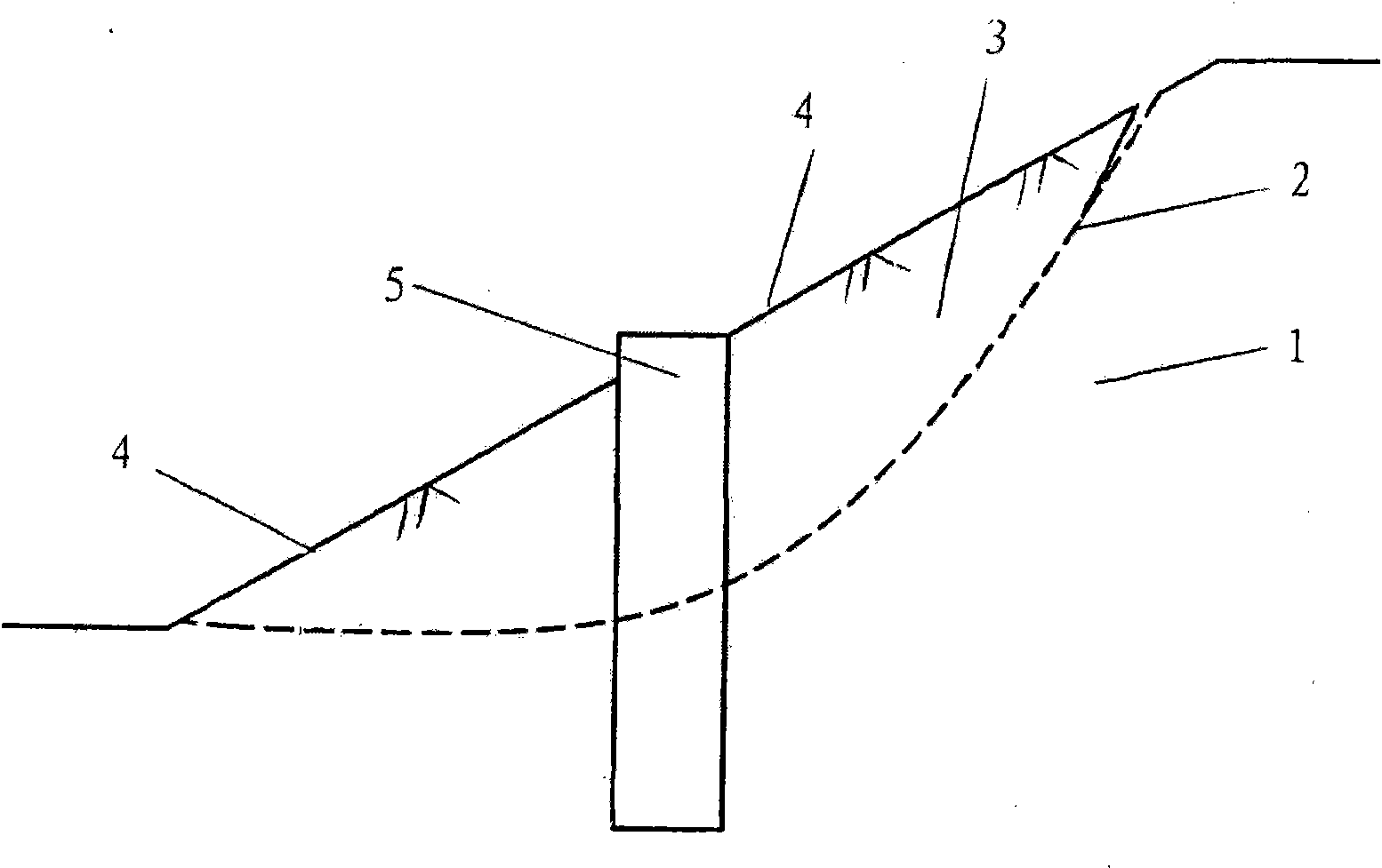
technical field [0001] The invention relates to foundation piles of foundation engineering, in particular to anchor tension anti-slide piles used as anti-sliding retaining structures for strengthening large-scale landslides. Background technique [0002] The anti-slide pile is to use the foundation pile of the foundation project as a support structure to strengthen the landslide. By passing through the landslide body and embedding the piles in the stable strata below the sliding surface, the anti-slide pile supports the sliding force of the landslide body and plays a role in stabilizing the landslide. [0003] figure 1 Shown is an existing monopile anti-slide retaining structure with anti-slide piles inserted directly into the landslide. like figure 1 As shown, the anti-slide pile 5 is a cylindrical or square column pile, which passes through the landslide body 3 and is embedded in the stable formation 1 below the sliding surface 2, and supports the sliding force of the la...

Claims


Application Information

Patent Timeline
Patent Type & Authority Patents(China)
IPC IPC(8): E02D17/20E02D5/76E02D5/38
Inventor 董捷宋绪国李国和
Owner CHINA RAILWAY DESIGN GRP CO LTD
Learn More