

A load-reducing rigid culvert structure
A culvert and rigid technology, applied in the field of load-relieving rigid culvert structures, can solve the problems of difficulty in realization, time-consuming and labor-intensive, affecting the load-reduction effect, etc., and achieve the effect of reducing the maximum bending moment and reducing the earth pressure on the top of the culvert.
- Summary
- Abstract
- Description
- Claims
- Application Information
AI Technical Summary
Problems solved by technology
Method used
Image

Examples
Embodiment 1
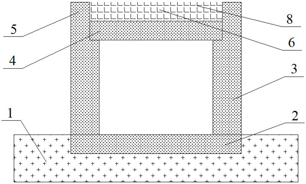
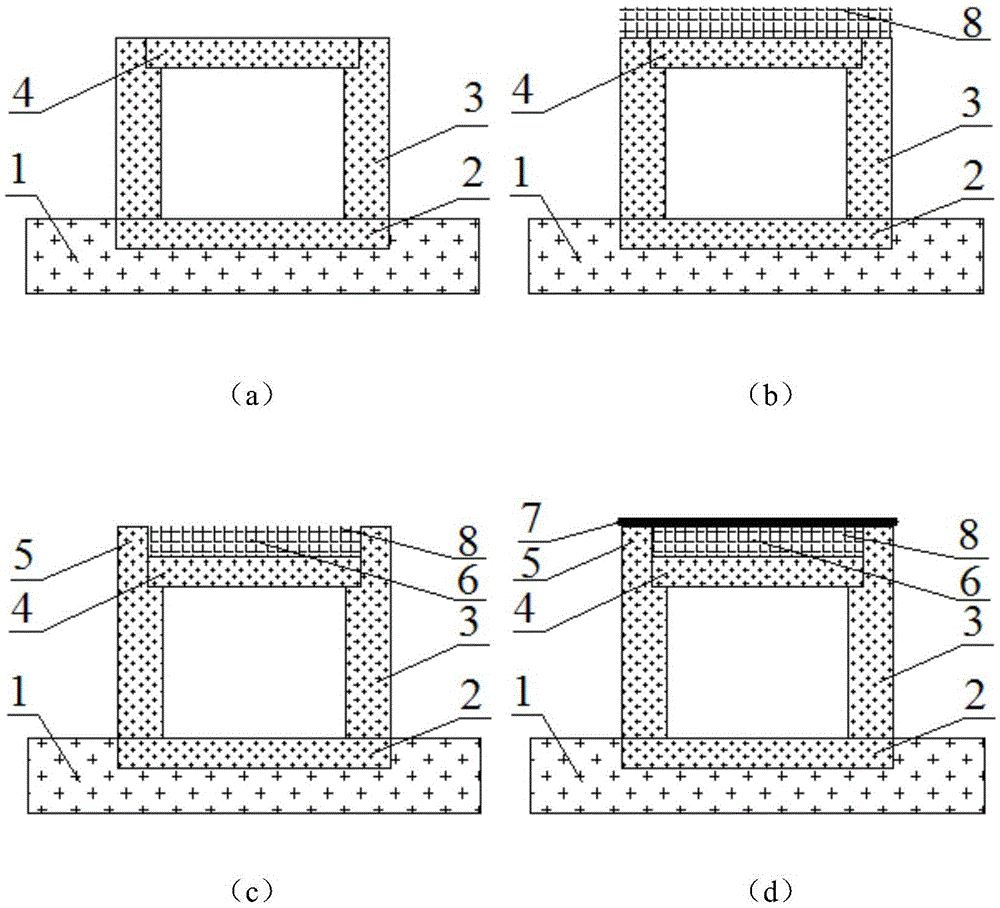
[0028] Such as figure 1 As shown, a load-reducing rigid culvert structure, the culvert is a cover culvert, including the foundation 2, the culvert side wall 3 and the culvert roof 4, and also includes a load-reducing block 5 and a load-reducing hole 6, and the load-reducing hole 6 filled with lightweight flexible material 8;
[0029] The foundation, the side wall of the culvert, the load-reducing block and the roof of the culvert are all reinforced concrete or plain concrete.
[0030] The load reducing block 5 is located directly above the top of the side wall 3 of the culvert, and is an integral structure with the side wall 3 of the culvert;
[0031] The length and width of the load-reducing block are consistent with the side wall of the culvert directly below it;
[0032] The load reduction hole 6 is located directly above the culvert roof 4 and is an open cavity surrounded by the culvert roof 4 and two load reduction blocks 5;
[0033] The depth of the load reduction hol...
Embodiment 2
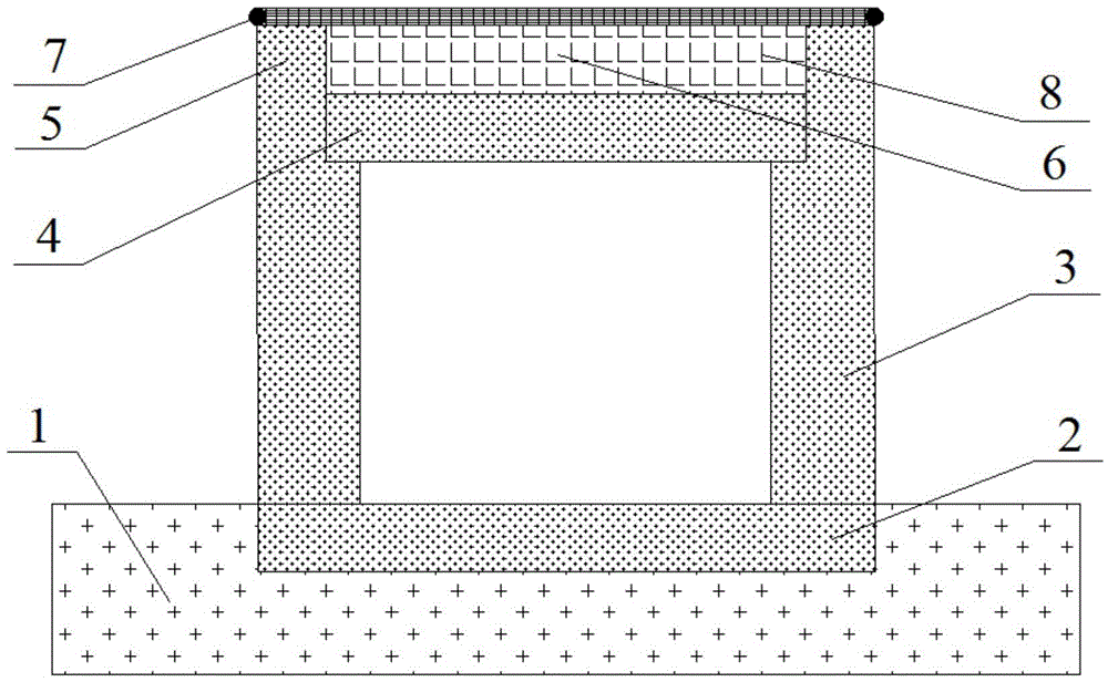
[0048] Such as figure 2As shown, a load-reducing rigid culvert structure, the culvert structure is mainly on the basis of embodiment 1, and additional reinforcements are laid. After the light flexible material 8 fills the load-reducing hole 6, a layer of reinforcement 7 is laid above the load-reduction hole, and the two sides of the reinforcement 7 are anchored on the outer edge of the top of the load-reduction block 5. It is not less than 1200kN / m, and it should be paved straight when laying; due to the increase of the tension film effect of the reinforcement, the upper part of the culvert side wall 3 is subjected to a pulling force that shrinks inward, so that the maximum bending moment on the culvert side wall 3 is reduced. Small, effectively reducing the impact of embankment fill on the force and deformation characteristics of the culvert side wall 3. In addition, the reinforcement material 7 produces deflection deformation under the action of the filling load, and the r...
PUM
 Abstract
Description
Claims
Application Information