Illumination device, display device, and method of manufacturing light modulator

A technology for lighting equipment and light modulators, which is applied to lighting and heating equipment, light guides of lighting systems, components of lighting devices, etc., can solve problems such as difficulty in realizing light source modulation, and achieve the effect of increasing illuminance

Active Publication Date: 2010-07-07
SONY CORP
View PDF3 Cites 17 Cited by
  • Summary
  • Abstract
  • Description
  • Claims
  • Application Information

AI Technical Summary

Problems solved by technology

However, it is difficult for the edge-light type backlight device to realize partial driving that partially modulates the light intensity of the light source.

Method used


Image

  • Illumination device, display device, and method of manufacturing light modulator
  • Illumination device, display device, and method of manufacturing light modulator
  • Illumination device, display device, and method of manufacturing light modulator

Examples


no. 1 example

[0050] 1. First embodiment (backlight device, normally white PDLC)

[0051] 2. Modification (location of light modulator, addition of optical sheet)

no. 2 example

[0052] 3. The second embodiment (backlight device, reverse PDLC)

[0053] 4. Application example (display device)

[0054] first embodiment

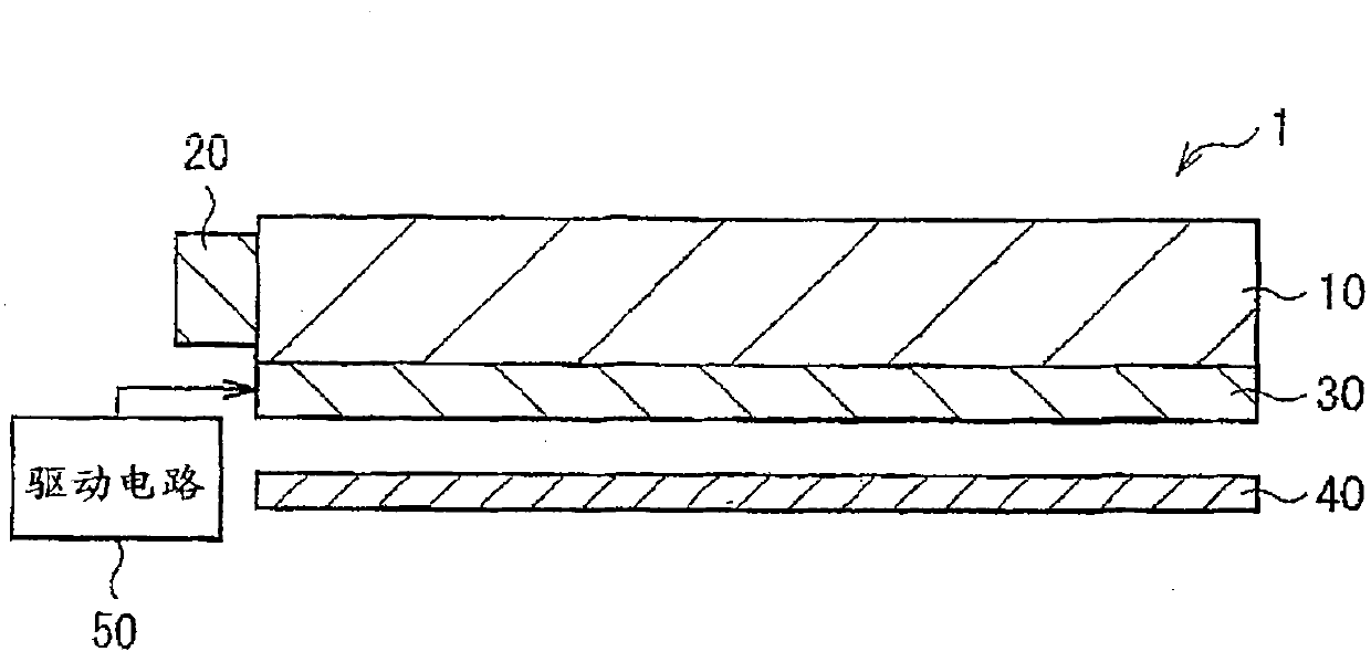
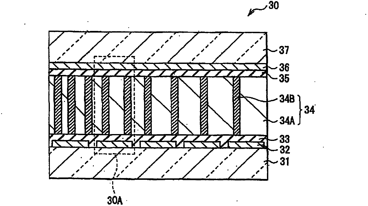
[0055] Figure 1A A cross-sectional configuration example of the backlight device 1 (illumination device) according to the first embodiment of the present invention is shown. Figure 1B shows the combination of Figure 1A An example of a cross-sectional configuration of a light modulator 30 (described later) in the backlight device 1 of . Figure 1A and 1B The examples are schematically shown, so the scale or shape is not limited to be the same as the actual scale or shape in the drawing. The backlight device 1 illuminates the liquid crystal display panel, for example, from the back of the liquid crystal display panel. board 40, and a drive circuit 50 for driving the light modulator 30.

[0056] The light guide plate 10 guides light from the light source 20 disposed on the side of the light guide plate 10 to the top of the light guid...


PUM


Abstract

An illumination device is provided and has a light guide plate, a light source and a light modulator, wherein the light modulator has a pair of transparent substrates a pair of electrodes and a light modulator layer. The light modulator layer includes a first region being changed between a transparent state and a scatterable state depending on intensity of an electric field, and a second region being more transparent than the first region in a scatterable state at an electric field having a certain intensity, the electric field being applied when the first region is changed between the transparent state and the scatterable state, and an occupancy rate of the first region in the light modulator layer is increased with increase in distance from the light source.

Description

technical field [0001] The present invention relates to a lighting device and a display device each having a light modulator that can scatter or transmit light and a method of manufacturing the light modulator. Background technique [0002] Recently, liquid crystal displays have been significantly improved in image quality or in power saving, and a method for improving dark-adapted contrast in which contrast is improved by partially modulating light intensity from a backlight device has been proposed. This method is mainly designed to partially drive a light emitting diode (Light Emitting Diode, LED) as a backlight light source, thereby modulating light from the backlight device according to a displayed image. In addition, thickness reduction is now increasingly required not only for small liquid crystal displays but also for large liquid crystal displays. Therefore, an edge type backlight device in which a light source is disposed at an end of a light guide plate has been ...

Claims


Application Information

Patent Timeline
Patent Type & Authority Applications(China)
IPC IPC(8): F21S8/00F21V8/00F21V9/00F21V14/00G02F1/13357G02F1/1333F21S2/00F21Y103/00G02F1/1334
CPCB29C66/82661B29C35/0894B29C2035/0827G09G3/3406B29L2009/003B29K2105/0079B29C65/7826G02F1/133615B29L2009/00B29C66/001B29L2031/747B29C66/433B29C66/45B29C66/472B29C66/474
Inventor 奥山健太郎佐藤晴美
Owner SONY CORP
Why Eureka
Try Eureka