Light guide module having embedded LED

Inactive Publication Date: 2005-05-12
SUNPLUS TECH CO LTD
View PDF2 Cites 58 Cited by
  • Summary
  • Abstract
  • Description
  • Claims
  • Application Information

AI Technical Summary

Benefits of technology

[0006] An object of the present invention is to provide a light guide module having an embedded LED so as to increase

Problems solved by technology

However, the prior art suffered from several disadvantages.
For example, it can significantly increase

Method used


Image

  • Light guide module having embedded LED
  • Light guide module having embedded LED
  • Light guide module having embedded LED

Examples


Example

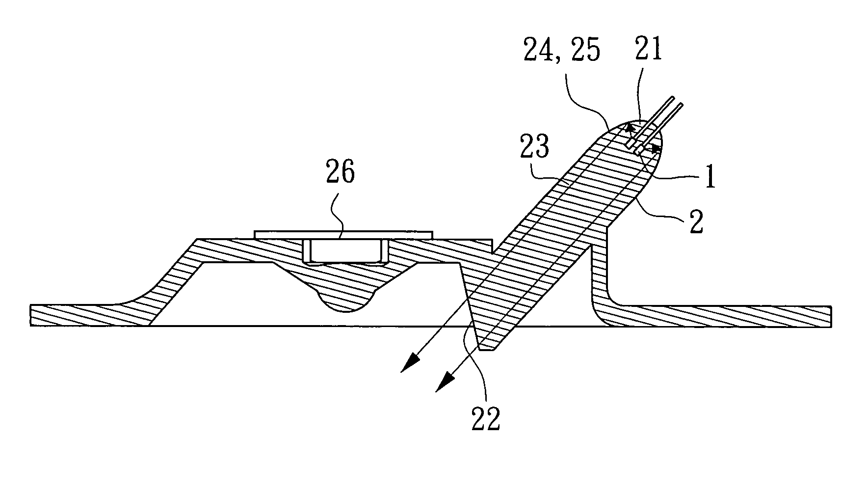
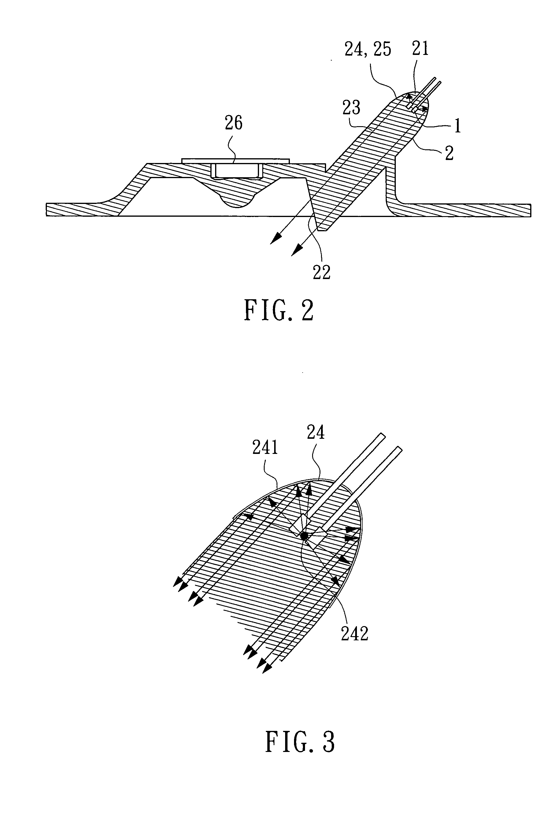
[0013] With reference to FIG. 2, there is shown a preferred embodiment of the invention. It comprises a LED die 1 and a light guide module 2. The light guide module 2 comprises a light guide input 21, a light guide output 22, and an optical path 23 between the light guide input 21 and the light guide output 22. Hence, input light from the light guide input 21 is adapted to output to the light guide output 22 via the optical path 23. As a result, light is able to impinge on the surface of an object.

[0014] The LED die 1 is disposed in the light guide input 21 of the light guide module 2. Light emitted from the LED die 1 is guided to the light guide output 22 via the optical path 23. The emitted light is transmitted to the light guide output 22 via a single medium (i.e., within the light guide module 2) since, as stated above, the LED die 1 is within the light guide module 2. This is contrary to the prior art which requires two transmissions via two different media before light can re...


PUM


Abstract

A light guide module of optical mouse is disclosed. The light guide module comprises a LED die within a light guide input of light guide means. The light guide input comprises an internal paraboloid. Light emitted by the LED die and parallel reflected from the paraboloid is impinged on a light guide output.

Description

BACKGROUND OF THE INVENTION [0001] 1. Field of the Invention [0002] The present invention relates to light guide module of optical mouse and, more particularly, to a light guide module of the optical mouse having an embedded LED (light emitting diode) with improved characteristics. [0003] 2. Description of Related Art [0004] Interior details of a conventional optical mouse are shown in FIG. 1. The optical mouse comprises a LED 4 as light source, an optical module 5 for guiding rays of light to a surface of a table, and an image sensor 7 within the optical mouse for receiving rays of light reflected from the surface. It is seen that the LED 4 is located outside the optical module 5. Also, a clip 6 is provided to fix the LED 4 in a predetermined position so as to substantially bring together rays of light emitted from the LED 4 to the optical module 5. [0005] However, the prior art suffered from several disadvantages. For example, it can significantly increase the manufacturing cost. ...

Claims


Application Information

Patent Timeline
IPC IPC(8): G02B6/00G02B6/42G06F3/03G06F3/033H01L33/54
CPCG02B6/00H01L33/54G06F3/0317G02B6/4214
Inventor CHU, CHI-CHUN
Owner SUNPLUS TECH CO LTD
Why Eureka
Try Eureka