LED replacement bulb

a technology of led replacement bulbs and led bulbs, which is applied in the direction of fibre light guides, lighting and heating apparatus, instruments, etc., can solve the problems of large power consumption of filament bulbs, increased power consumption, and inability to meet the needs of users, so as to improve efficiency and illumination, and improve the efficiency of light directed out of the module

Inactive Publication Date: 2006-08-31
VARROC LIGHTING SYST SRO
View PDF25 Cites 60 Cited by
  • Summary
  • Abstract
  • Description
  • Claims
  • Application Information

AI Technical Summary

Benefits of technology

[0005] The present invention provides a LED bulb and light module which utilizes a LED light source and directs light therefrom in a manner which improves efficiency and illumination. The LED bulb is structured to create a virtual image whereby the efficiency of light directed out of the module is greatly improved, even with a single LED light source. The LED bulb generally includes a light pipe receiving light from the LED light source which guides the light downstream along a longitudinal axis. A downstream portion of the light pipe defines a first curved surface and a second curved surface. The second curved surface is spaced radially outward of the first curved surface. The first and second curved surfaces redirect the light radially outwardly to define a virtual image of the LED light source.

Problems solved by technology

While such modules have a long and successful history, filament bulbs consume a large amount of power and have a relatively short life.
Unfortunately, LED solutions also have their drawbacks.
In particular, automotive light assemblies utilizing LED light sources typically use a large number LED's, typically eight or more, which thus requires increasing amounts of power over a single LED bulb.
Furthermore, these light modules using LED light sources suffer from poor efficiency, that is, the amount of original light from the light source which is actually directed outwardly away from the vehicle to illuminate the surrounding area.

Method used


Image

  • LED replacement bulb
  • LED replacement bulb
  • LED replacement bulb

Examples


Embodiment Construction

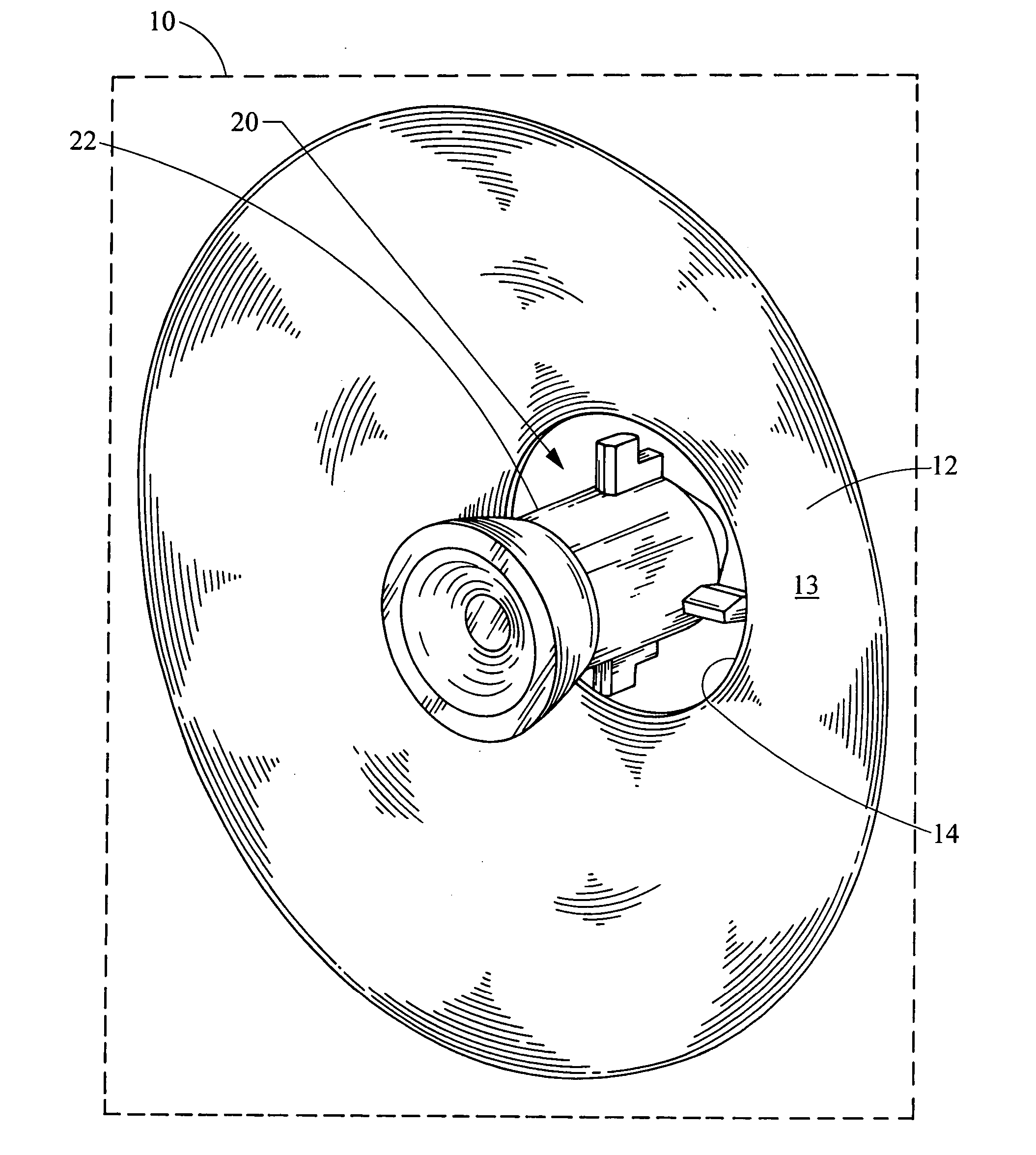
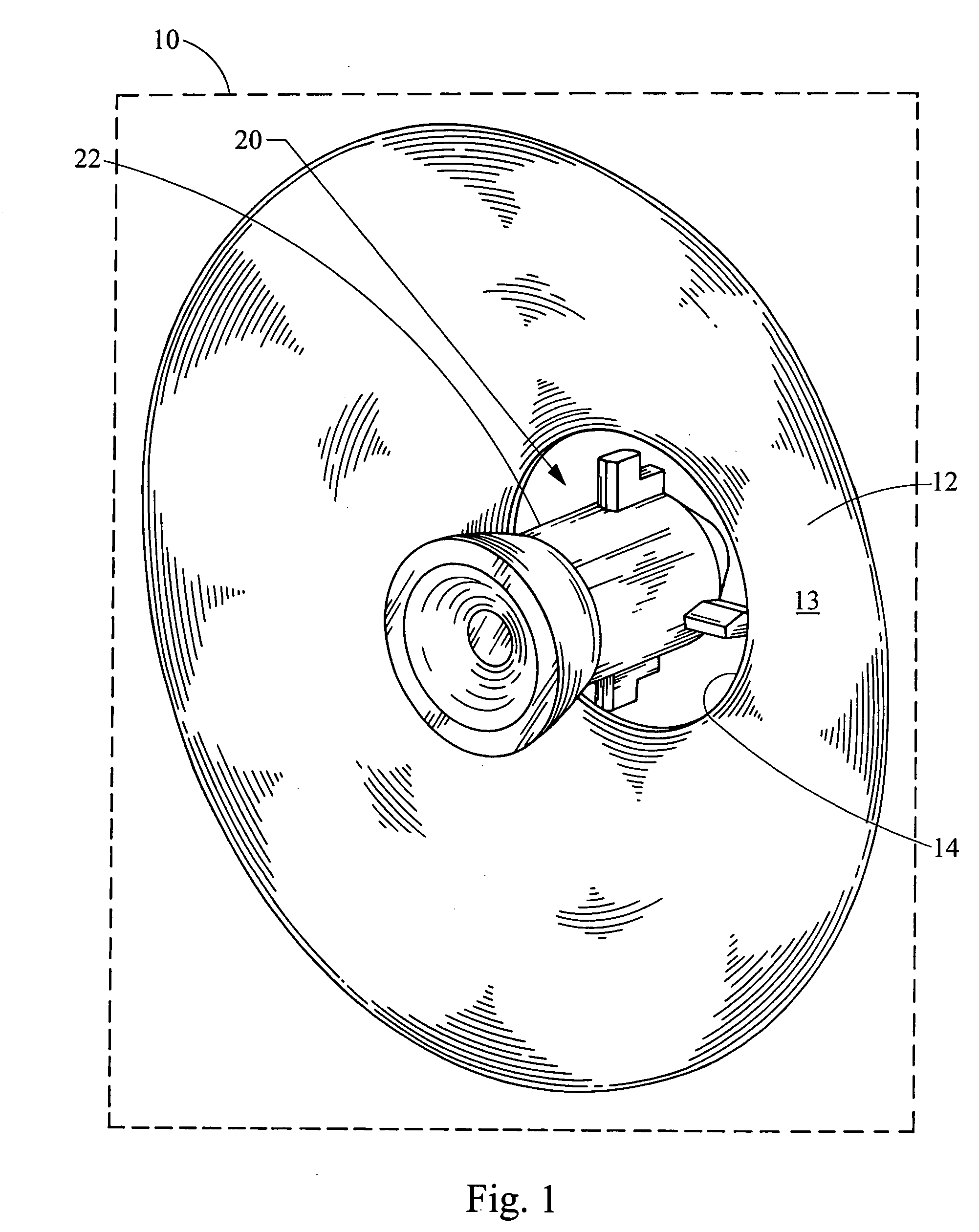
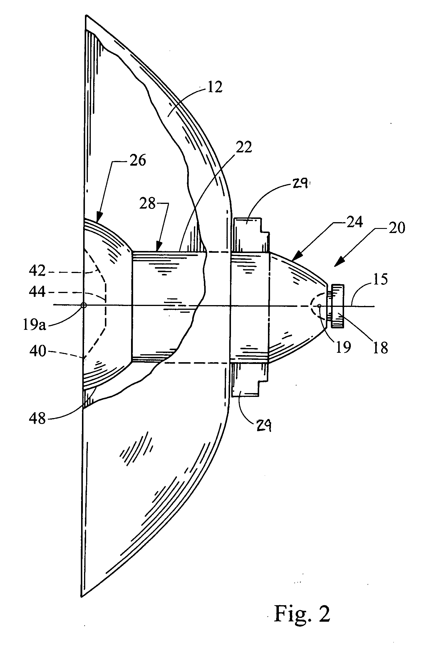
[0014] Turning now to the figures, FIG. 1 depicts a perspective view of a light module 10 having a LED bulb 20 constructed in accordance with the teachings of the present invention. Among other things, the light module 10 includes a reflector 12 defining a reflective surface 13 which receives light from the LED bulb 20 and directs the light outwardly away from the vehicle. The reflector 12 includes an opening 14 which receives an LED bulb 20. The bulb 20 is generally defined by a light pipe 22 which extends through the opening 14 in the reflector 12. The light pipe 22 directs light received from a LED light source 18 (FIG. 2).

[0015] The details of the LED bulb 20 will now be described with reference to FIGS. 2 and 3. The entire light pipe 22 is generally integrally formed, and preferably is formed by injection molding a clear optical grade material, although it will be recognized that the light pipe 22 may be formed in several parts and through other manufacturing techniques. The m...


PUM


Abstract

A LED bulb and light module utilizes a LED light source and directs light therefrom in a manner which improves efficiency and illumination. Ideally, the LED bulb is structured to create a virtual image whereby the efficiency of light directed out of the module is greatly improved, even with a single LED light source. The LED bulb generally includes a light pipe receiving light from the LED light source and guides the light downstream to a downstream portion which redirects the light radially outwardly.

Description

FIELD OF THE INVENTION [0001] The present invention relates generally to a light module for a motor vehicle, and more particularly relates to an LED bulb for use in such a light module. BACKGROUND OF THE INVENTION [0002] Modern automotive light modules typically use a filament bulb as their light source. While such modules have a long and successful history, filament bulbs consume a large amount of power and have a relatively short life. In an attempt to overcome these shortcomings, others have proposed to utilize LED light sources to replace the filament bulbs since LED's consume significantly less power and have a long life span. [0003] Unfortunately, LED solutions also have their drawbacks. In particular, automotive light assemblies utilizing LED light sources typically use a large number LED's, typically eight or more, which thus requires increasing amounts of power over a single LED bulb. Furthermore, these light modules using LED light sources suffer from poor efficiency, that...

Claims


Application Information

Patent Timeline
Patent Type & Authority Applications(United States)
IPC IPC(8): F21V5/00
CPCF21K9/00F21K9/52F21V5/002F21V5/04F21V7/0091F21V13/04F21Y2101/02G02B6/0008G02B6/0018G02B6/002G02B6/0045F21S48/115F21S48/1225F21S48/1329F21S48/215F21S48/2212F21S48/236F21S48/24F21W2101/10F21W2101/14F21K9/61F21Y2115/10F21K9/68F21S41/143F21S41/285F21S41/322F21S43/14F21S43/26F21S43/315F21S43/40F21W2103/00F21W2102/00
Inventor CHINNIAH, JEYACHANDRABOSEERION, JEFFREY ALLENEICHELBERGER, CHRISLI, JOHN
Owner VARROC LIGHTING SYST SRO
Why Eureka
Try Eureka