Check patentability & draft patents in minutes with Patsnap Eureka AI!

Laser lock imaging method and device

A technology of laser and modulated laser, which is applied in the field of electronic information, can solve the problem of not being able to obtain visible light images, and achieve the effect of increasing the sampling frequency

Inactive Publication Date: 2010-07-07
UNIV OF ELECTRONICS SCI & TECH OF CHINA
View PDF0 Cites 5 Cited by
  • Summary
  • Abstract
  • Description
  • Claims
  • Application Information

AI Technical Summary

Benefits of technology

This patented technology improves how we detect objects without actually measuring them accurately through reflection off their surfaces. It uses filters made up of multiple layers to block unwanted lights like sunlight during certain phases of operation. By doing this, our device becomes more accurate over time because less energy needs to be absorbed compared to traditional methods such as lensless cameras.

Problems solved by technology

Technological Problem: Existing techniques involve capturing images without any clear indications about hidden areas within the subject being observed while avoiding harm caused by external lights like brightness or darkness. Additionally, current cameras suffer from insufficient contrast between dark and non-bright spots during daytime because they lack sufficient sensitivity.

Method used


Image

  • Laser lock imaging method and device
  • Laser lock imaging method and device
  • Laser lock imaging method and device

Examples


Embodiment Construction

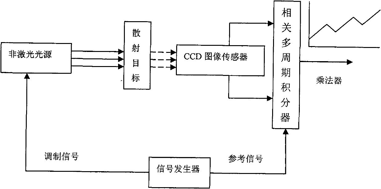
[0037] Specific technical solutions such as image 3 As shown, the sinusoidal signal generated by the sinusoidal signal generator is used to modulate the laser generated by the semiconductor laser, so that the semiconductor laser generates a sinusoidal signal to modulate the laser. After the laser and background light are filtered by optical filters, they are collected by the CCD focal plane array at a constant speed to obtain a series of sensing images of the target field of view; the sinusoidal signal generated by the sinusoidal signal generator and the target field of view collected by the CCD focal plane array are The sensing image of the field is stored in the memory in the video processing circuit, and the phase detection processing of the sensing image of the target field of view is completed by the video processing circuit: that is, within one or an integer number of sinusoidal modulation cycles, the CCD focal plane array is collected Each sensing image in the target f...


PUM


Abstract

The invention discloses a laser lock imaging method and a device, which belongs to the technical field of electronic information and relates to an image processing technique. Periodically modulated laser is adopted to irradiate a target area, partial background light in a target viewing field is filtered by optical filtering and is then processed by phase demodulation which is detected by weak signals, and a target image in the target viewing field is extracted from the strong background light. By using the method and the device, the clear target image can be extracted from the strong background light, and the background light suppression ability is great. The method and the device can be applied to aiming systems in traffic monitoring, industrial monitoring and weapon equipment and night-vision equipment.

Description


Claims


Application Information

Patent Timeline
Owner UNIV OF ELECTRONICS SCI & TECH OF CHINA
Features
  • R&D
  • Intellectual Property
  • Life Sciences
  • Materials
  • Tech Scout
  • Unparalleled Data Quality
  • Higher Quality Content
  • 60% Fewer Hallucinations
Learn More