Shear wall multifunctional positioning element

A multi-functional, positioning component technology, applied in the direction of building components, building reinforcements, structural elements, etc., can solve the problems of increasing construction costs, insufficient bending strength, affecting construction accuracy, etc., to achieve easy construction and installation, self-lubricating Good, easy processing effect

Inactive Publication Date: 2011-12-07
林光明
View PDF7 Cites 0 Cited by
  • Summary
  • Abstract
  • Description
  • Claims
  • Application Information

AI Technical Summary

Problems solved by technology

It has a simple structure and overcomes the defect of the left and right offset of the positioning hook, but when it is positioned during construction, it is necessary to use thin iron wires to bind the two ends of the positioning hook to the steel mesh respectively, which brings trouble to the construction and wastes man-hours. The product is made of steel bars, which cost a lot. If steel bars with smaller diameters are used, the bending strength will not be enough, which will affect the construction accuracy. If steel bars with large diameters are used, although the strength required for construction is achieved, the manufacturing cost is expensive. thereby increasing construction costs

Method used


Image

  • Shear wall multifunctional positioning element
  • Shear wall multifunctional positioning element
  • Shear wall multifunctional positioning element

Examples


Embodiment 1

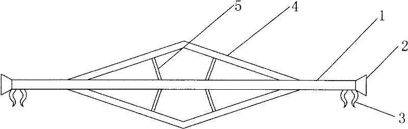
[0019] Such as figure 1 As shown, a multifunctional positioning member for a shear wall includes a positioning rod 1, pads 2 are provided at both ends of the positioning rod 1, and a hook 3 is provided on the positioning rod 1 inside the two pads 2, and the two hooks 3 Several herringbone ribs 4 uniformly distributed in the circumferential direction are arranged on the positioning rod 1 inside. The cross-sectional shape of positioning rod 1 is any one in circle, square, triangle, regular polygon, preferably with circle, and positioning rod 1 is a solid rod body; The cross-sectional shape of rib 4 is circular, square, triangular, Any one of regular polygons, circle and square are preferred. The positioning rod 1, the spacer 2, the hook 3 and the reinforcing rib 4 are of an integrated structure and are made of engineering plastics. The shape of the spacer 2 is a circular platform with a large outside and a small inside, and its interface shape is an isosceles trapezoid. The h...

Embodiment 2

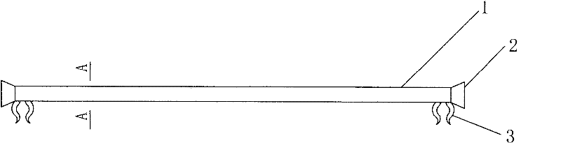
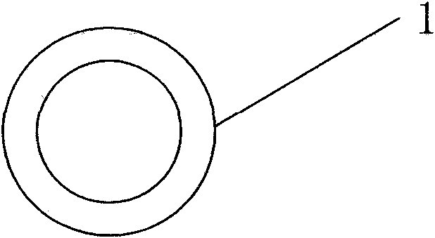
[0021] Such as figure 2 , image 3 As shown, a multifunctional positioning member for a shear wall, the basic structure of this embodiment is the same as that of Embodiment 1, the difference is that the positioning rod 1 is a hollow rod body, and no reinforcing ribs are added on the positioning rod 1, in order to ensure that the positioning member The strength of bending resistance, so when making, the outer diameter of the positioning rod 1 of this embodiment is relatively larger than the diameter of the positioning rod 1 in embodiment 1. The solution of this embodiment is: including positioning rod 1, positioning rod 1 Pads 2 are provided at both ends of the two pads 2, and a hook 3 is provided on the positioning rod 1 inside the two pads 2. The positioning rod 1 adopts a rod body with a hollow structure in the middle, and the external profile of the rod is still circular, square, triangular, positive Either of the polygons, image 3 It is the cross-sectional shape of the...


PUM


Abstract

The invention discloses a multifunctional positioning part for a shear wall, which belongs to the technical field of building components, and includes a positioning rod, pad blocks are provided at both ends of the positioning rod, and hooks are provided on the positioning rod inside the two pad blocks. The beneficial effect is that the structure is simple, the effect of pulling and positioning the shear wall is remarkable, and the construction and installation are convenient, and the thickness of the protective layer of the shear wall and the overall thickness of the shear wall can be effectively controlled to meet the specification required by the construction. The structure is easy to process, can be produced in batches, prevents the corrosion phenomenon of the wall body, and ensures the beauty of the wall surface.

Description

technical field [0001] The invention discloses a multifunctional positioning part for a shear wall, which belongs to the technical field of building components. Background technique [0002] The shear wall structure is a concrete structure commonly used in high-rise buildings. The shear wall is formed by setting up a formwork outside the steel skeleton, and then pouring concrete into it. The reinforced skeleton includes double rows of steel meshes set up parallel to each other according to the spacing required by conventional construction, and the double rows of steel meshes are connected by positioning hooks. The spacing is consistent up and down. After the total thickness of the wall is determined according to the requirements of the building code, the formwork is supported outside the steel skeleton, and the distance between the formwork and the steel bars on each side is equal, because the positioning hook can only control the distance between the double rows of steel b...

Claims


Application Information

Patent Timeline
Patent Type & Authority Patents(China)
IPC IPC(8): E04C5/16
Inventor 林光明
Owner 林光明
Why Eureka
Try Eureka