
Indoor omnidirectional antenna

An omnidirectional antenna and antenna technology, which is applied in antenna coupling, antenna unit combinations with different polarization directions, etc., can solve the problem that omnidirectional antennas cannot meet dual-polarization requirements.

Inactive Publication Date: 2013-02-06
MOBILE ANTENNA TECH SHENZHEN
View PDF0 Cites 0 Cited by
  • Summary
  • Abstract
  • Description
  • Claims
  • Application Information

AI Technical Summary

Problems solved by technology

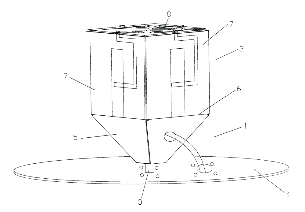
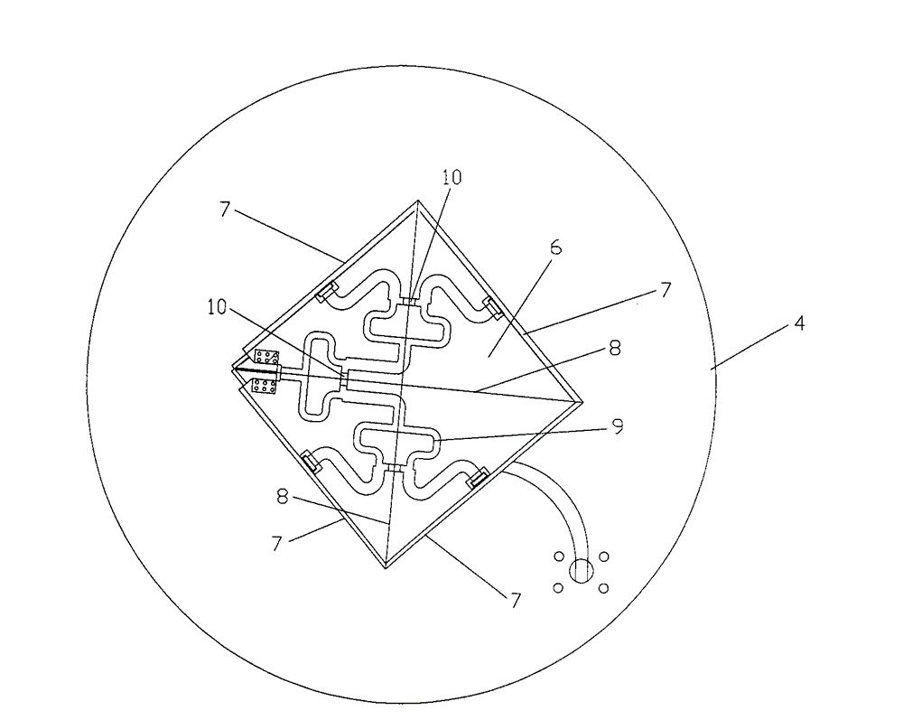
[0003] The purpose of the embodiments of the present invention is to provide an indoor omnidirectional antenna, which aims to solve the problem that the existing indoor omnidirectional antenna cannot meet the requirements of dual polarization

Method used


Image

  • Indoor omnidirectional antenna
  • Indoor omnidirectional antenna
  • Indoor omnidirectional antenna

Examples


Embodiment Construction

[0009] In order to make the object, technical solution and advantages of the present invention clearer, the present invention will be further described in detail below in conjunction with the accompanying drawings and embodiments. It should be understood that the specific embodiments described here are only used to explain the present invention, not to limit the present invention.

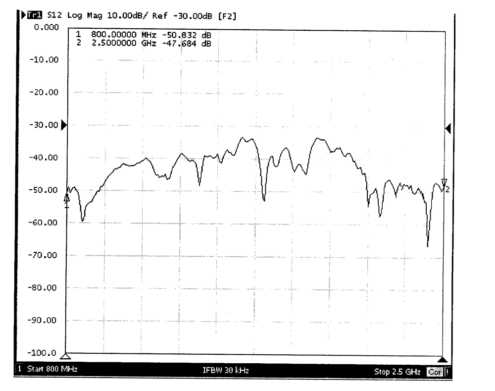
[0010] The difference between the embodiments of the present invention and the prior art is that the indoor omnidirectional antenna includes a vertically polarized antenna and a horizontally polarized antenna arranged in the axial direction of the vertically polarized antenna, and the horizontally polarized antenna and the vertically polarized A partition is provided between the antennas to improve the non-correlation (that is, isolation) between the horizontal polarization and the vertical polarization, and to meet the requirements of the LTE system for indoor omni-directional antenna dual polariza...


PUM


Abstract

The invention is applied to transmitting indoor signals and provides an indoor omnidirectional antenna. The omnidirectional antenna comprises a vertical polarized antenna which is axially provided with a horizontally-polarized antenna, wherein a baffle wall is arranged between the horizontally-polarized antenna and the vertical polarized antenna. The baffle wall promotes the non-relevance (i.e. isolation degree) between the horizontally-polarized antenna and the vertical polarized antenna of the indoor omnidirectional antenna and meets the demand of the LTE system on double polarizing the indoor omnidirectional antenna. The horizontally-polarized antenna and the vertical polarized antenna meet the technical demand of MIMO (Multiple-Input Multiple-Out-put).

Description

technical field [0001] The invention belongs to the technical field of antennas, in particular to an indoor omnidirectional antenna. Background technique [0002] 2G systems (such as CDMA and GSM systems) use electromagnetic waves with a frequency of 800-900 MHz. The electromagnetic waves in these frequency bands have strong penetration capabilities and indoor signals are better. Most of the 3G systems use electromagnetic waves with a frequency of about 2000MHz, and the ability of electromagnetic waves in this frequency band to penetrate buildings is relatively weak. As the frequency used by LTE (Long Term Evolution, Long Term Evolution) further increases, the ability of its electromagnetic waves to penetrate buildings is further weakened, and more blind spots will be formed indoors, and most data services will occur indoors in the future. At present, indoor antennas are basically omnidirectional single-polarized antennas, which cannot meet the dual-polarized omnidirectiona...

Claims


Application Information

Patent Timeline
Patent Type & Authority Patents(China)
IPC IPC(8): H01Q21/24H01Q1/52
Inventor 侯小强韩香紫张友强刘前昌
Owner MOBILE ANTENNA TECH SHENZHEN
Learn More