Ratio meter for temperature sensor

A ratio and frequency technology, applied in the field of ratiometers for temperature sensors, can solve problems such as temperature errors, increased area and power consumption, and increased measurement errors

Inactive Publication Date: 2012-12-05
INTEL CORP
View PDF0 Cites 0 Cited by
  • Summary
  • Abstract
  • Description
  • Claims
  • Application Information

AI Technical Summary

Problems solved by technology

These side effects can increase measurement errors e.g. caused by differences in DAC performance between calibration and system operation
Also, when switching between different sets of current sources, the above variations can make the current a non-monotonic function of the digital bits
This can cause significant temperature errors
Another problem could be the poor PSRR (Power Supply Rejection Ratio) of the DAC, which typically requires a good SFR (super filtered regulator) to power the DTS
Increasing SFR results in increased area and power consumption and additional need for calibration

Method used


Image

  • Ratio meter for temperature sensor
  • Ratio meter for temperature sensor
  • Ratio meter for temperature sensor

Examples


Embodiment Construction

[0017] In some embodiments, a new DTS implementation is provided that can employ the existing Vbe / ΔVbe temperature correlation principle, but replace the DAC-based ratiometer with a voltage-frequency (V / F)-based ratiometer. This new approach can lead to a more simplified circuit that is more tolerant to variation and can require less power and area.

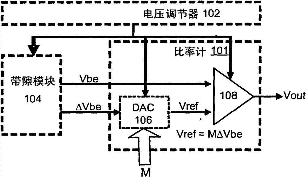
[0018] Figure 4 A schematic diagram of a DTS according to some embodiments is shown. The DTS includes a ratiometer 401 with a voltage-to-frequency (V / F) converter (or oscillator) 404 (V / F1), 406 (V / F2) and a frequency divider ( F1 / F2) 408, the ratiometer 401 is coupled to the existing bandgap circuit 104 as shown to provide a temperature factor M whose value corresponds to the temperature in the bandgap circuit. Bandgap circuit 104 includes a diode-based PTAT module that generates two temperature-dependent DC voltages, Vbe and ΔVbe. In some bandgap circuits, ΔVbe may sometimes be referred to as Vref, etc. (See, e.g., "A CMOS ...


PUM


Abstract

In some embodiments, a new DTS implementation, which employs the conventional Vbe/ΔVbe temperature dependent principles but substitutes a voltage-to-frequency (V/F) based ratio meter for the DAC based approach. This new approach can result in a more simplified circuit that may be more variation tolerant and can require less power and area.

Description

Background technique [0001] FIG. 1 shows an existing digital temperature sensor (DTS) using a known type of bandgap circuit 104 coupled with an existing ratio meter circuit 101 . The ratiometer circuit 101 includes a current source based DAC (Digital to Analog Converter) 106 to generate a temperature dependent function M (multiplier for the DAC) based on zeroing the Vout value output by the comparator 108 . The bandgap circuit 104 may include a standard diode based PTAT (Proportional to Absolute Temperature) module that generates two temperature dependent DC voltages Vbe and ΔVbe. In some embodiments, the Vbe voltage has a negative temperature slope, while the ΔVbe voltage has a positive or flat temperature slope. The ΔVbe voltage is multiplied by a factor M by the DAC 106 . DAC 106 may include an existing current source DAC such as that shown in FIG. 2 . In this example, M is a discrete 4-bit value corresponding to an analog level, which is multiplied by ΔVbe, resulting in...

Claims


Application Information

Patent Timeline
Patent Type & Authority Patents(China)
IPC IPC(8): G01K7/00G01K7/02
CPCG01K2219/00G01K7/01
Inventor K·卢里亚J·绍尔O·达德谢乌
Owner INTEL CORP
Why Eureka
Try Eureka