

Method for removing clamp strip type stone plates
A strip type, stone material technology, applied in building maintenance, building components, walls, etc., can solve the problems of time-consuming and consumable materials, increase engineering costs, etc., and achieve the effect of saving engineering costs, strong applicability, and simple and effective methods
- Summary
- Abstract
- Description
- Claims
- Application Information
AI Technical Summary
Problems solved by technology
Method used
Image

Examples
Embodiment Construction
[0022] The specific steps of the present invention to replace the clip-type stone panel are:
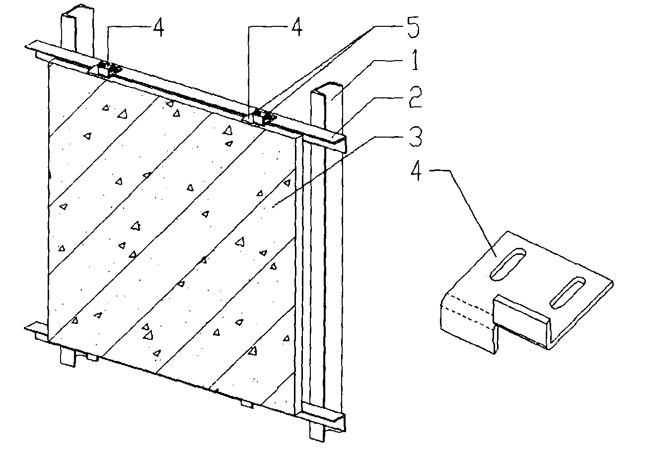
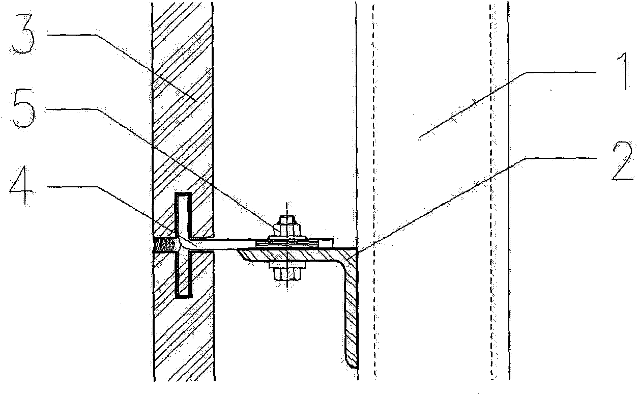
[0023] 7. Remove the damaged panel 3, and cut off the part of the clip 4 used to fix the panel 3, that is, the clip 4 on the upper part of the panel 3 cuts off the downward bend, and the clip 4 on the lower part of the panel 3 cuts off the upward fold. Bend, then clean up the card strip 4;
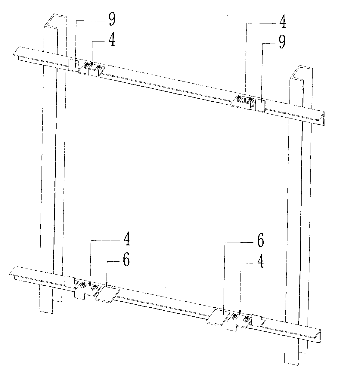
[0024] 8. Weld two steel pallets 6 at the position of the original clip 4 at the lower part of the panel to support the weight of the replaced stone panel 7, and apply anti-corrosion paint to the welded part after welding;
[0025] 9. Weld the inner clamping strip 9 at the position corresponding to the notch of the stone panel 7 on the beam 2, and apply anti-corrosion paint to the welding part after welding. Here, attention should be paid to the connection position of the inner clamping strip and the beam: the upper end surface of the upper inner clamping strip is flush with the lower end surfac...
PUM
 Abstract
Description
Claims
Application Information