

Pressure reducing valve
A pressure reducing valve and pressure technology, which is applied in the field of pressure reducing valves, can solve the problems of cost increase and other problems, and achieve the effects of improving sealing performance, reducing cost and realizing weight reduction
- Summary
- Abstract
- Description
- Claims
- Application Information
AI Technical Summary
Problems solved by technology
Method used
Image

Examples
Embodiment 1
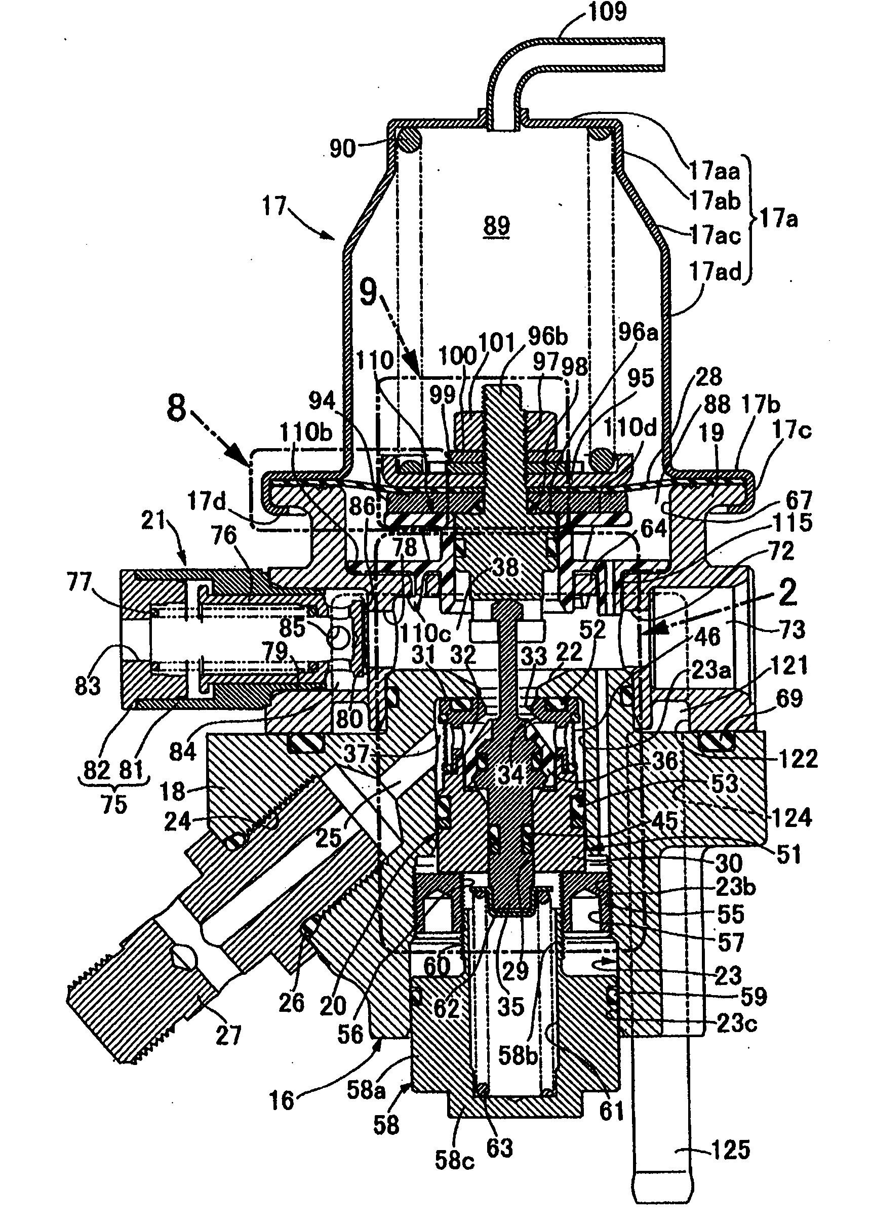
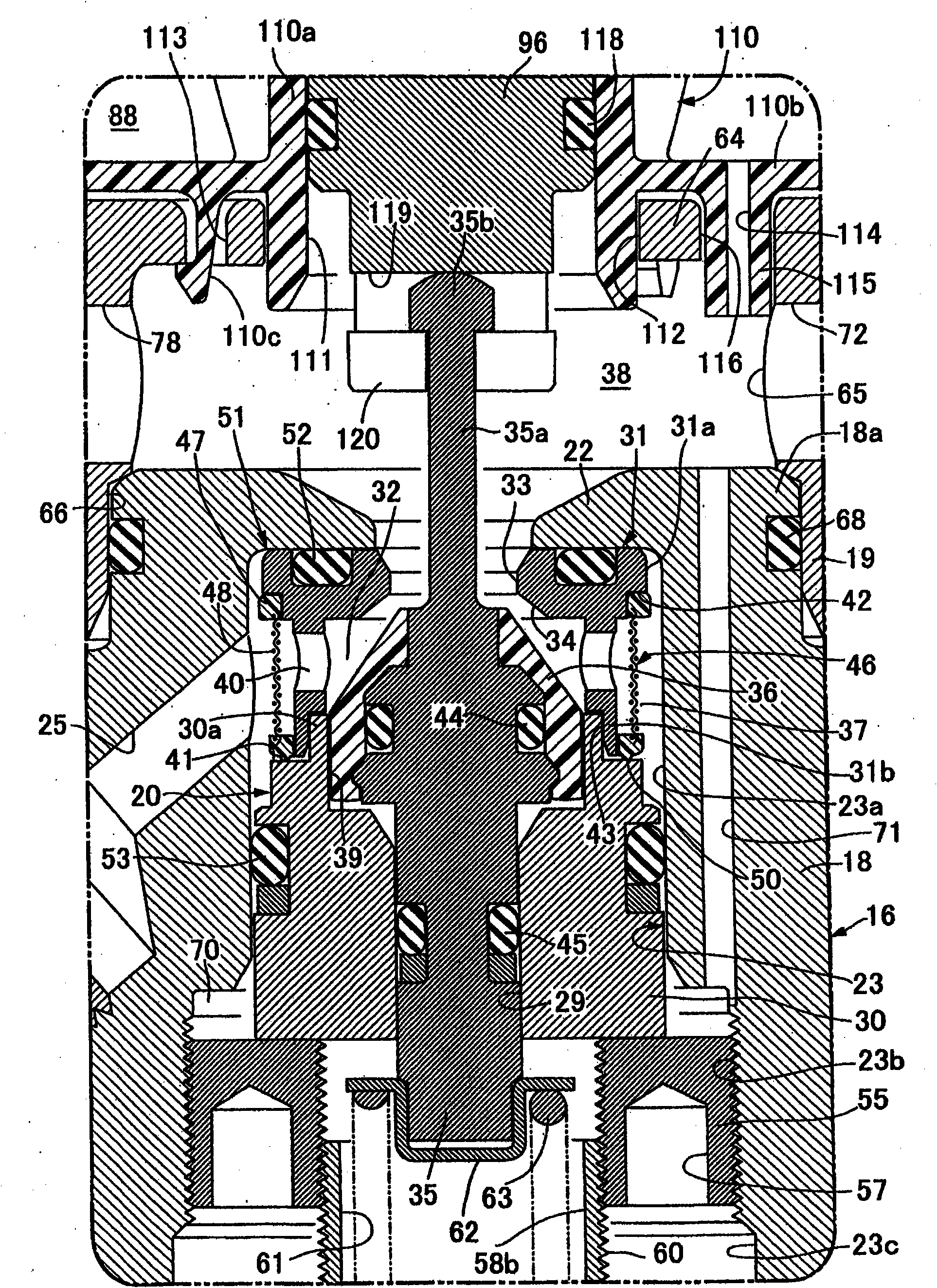
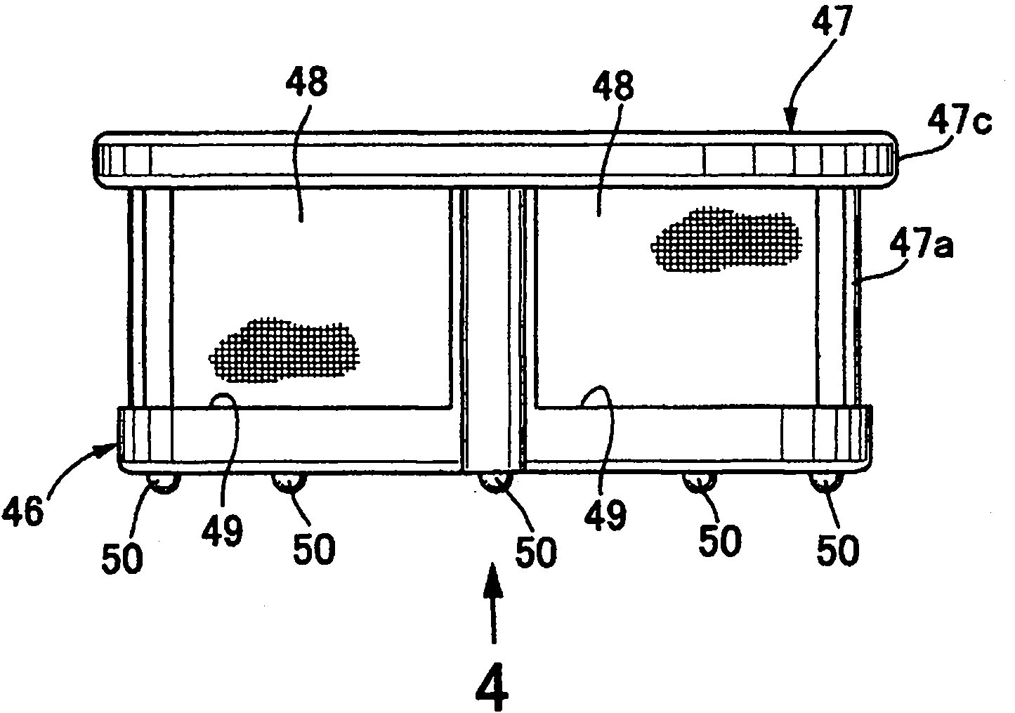
[0049] Figure 1 to Figure 14 shows an embodiment of the present invention.
[0050] First, in figure 1 Among them, the pressure reducing valve for gas is used to depressurize compressed natural gas as fuel gas and supply it to the engine (not shown), and the pressure reducing valve for gas includes: The main body 16 which is combined and constituted, and the diaphragm cover 17 which is combined with the main body 16, the valve mechanism 20 is housed in the said main body 16, and the relief valve 21 is arrange|positioned.
[0051] The main body 16 is configured by stacking the first main body member 18 and the second main body member 19 up and down and fastening them at multiple places. A receiving hole 23 is provided in the central part of the first main body part 18. The receiving hole 23 extends in the vertical direction and has an inward shoulder 22 protruding radially inward at the upper end. The receiving hole 23 passes through the inward shoulder. From the 22 side, t...
PUM
 Abstract
Description
Claims
Application Information