Storage device comprising turbulating means

A kind of equipment and turbulent flow technology, applied in the field of storage equipment, can solve problems such as adverse greenhouse effects and achieve low cost effects

Active Publication Date: 2014-11-26
VALEO SYST THERMIQUES
View PDF6 Cites 0 Cited by
  • Summary
  • Abstract
  • Description
  • Claims
  • Application Information

AI Technical Summary

Problems solved by technology

However, R134a has a very adverse greenhouse effect, which is not the case for HFO1234YF

Method used


Image

  • Storage device comprising turbulating means
  • Storage device comprising turbulating means
  • Storage device comprising turbulating means

Examples


Embodiment Construction

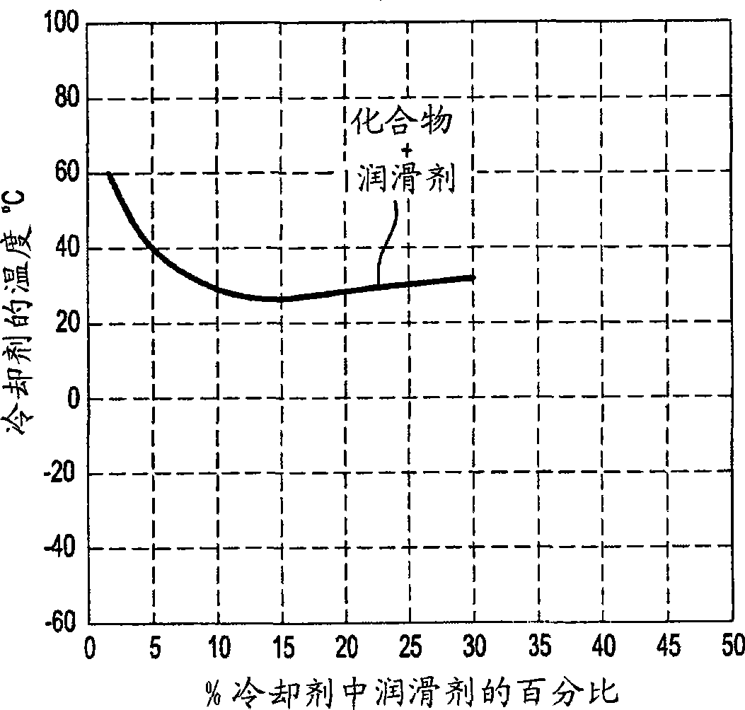
[0033] figure 1 A technical problem is indicated. It shows a two-dimensional graph where the x-axis represents the percentage of lubricant in the coolant, from 0% on the left to 50% on the right. The y-axis of the graph represents the temperature of the coolant in the circuit measured at the inlet of the storage device according to the invention. The black curve titled "Compound + Lubricant" represents the behavior of compound and lubricant mixtures such as the group known by the acronym HFO1234YF mixed with an oil or lubricant known to be labeled 100PAG point. It should be noted that at 30°C, the percentage of oil in the coolant is 10%, which is greater than the commonly known oil return rate of eg 5% for fixed displacement compressors. Therefore, it should be understood that the coolant delivers enough oil to prevent compressor degradation. However, for air-conditioning circuits operating at high outside temperatures (greater than 35°C) or in traffic jams (low speed), th...


PUM


Abstract

The device (1) has an inlet tube (18) for inletting refrigerant, and an outlet tube (19) for outletting the refrigerant, where the refrigerant is formed by a mixture of chemical compound i.e. 2,3,3,3-Tetrafluoropropene, and a lubricant. A storage zone (10) stores the refrigerant. A communication unit (16) causes turbulences in the storage zone. The communication unit is in the form of a manifold (13) that channels the refrigerant from an intake chamber (9) to the storage zone. The inlet tube traverses an evacuation chamber separated from the storage zone by a plate.

Description

technical field [0001] The invention relates to the field of air-conditioning circuits, which cooperate with heating, ventilation and / or air-conditioning systems of motor vehicles. The invention relates to storage devices used in such circuits, known as cylinders or accumulators. The invention also relates to an air conditioning circuit comprising such a storage device. Background technique [0002] Motor vehicles are usually equipped with heating, ventilation and / or air conditioning systems in order to regulate the aerothermal parameters of the air contained inside the vehicle. Such a system cooperates with an air conditioning circuit to cool the air flow before it is delivered from the circuit to the interior of the vehicle. The circuit comprises a plurality of elements or parts in which the following components circulate continuously: a component such as a subcritical fluid, in particular HFO1234YF mixed with a known lubricant, which For example marked as ISO100PAG or ...

Claims


Application Information

Patent Timeline
Patent Type & Authority Patents(China)
IPC IPC(8): F25B41/00F25B43/00
CPCF25B2500/18F25B2400/03F25B43/006F25B2400/02F25B2400/16
Inventor 艾梅德·吉塔里
Owner VALEO SYST THERMIQUES
Why Eureka
Try Eureka