
Feeding device with grate

Technology of a feeding device, grate, applied in the field of feeding animals

Inactive Publication Date: 2010-08-11
ACO FUNKI
View PDF2 Cites 2 Cited by
  • Summary
  • Abstract
  • Description
  • Claims
  • Application Information

AI Technical Summary

Problems solved by technology

[0003] While the feeder itself is a success, this bridging phenomenon is the biggest drawback

Method used


Image

  • Feeding device with grate
  • Feeding device with grate
  • Feeding device with grate

Examples


Embodiment Construction

[0031] In the drawings, the same or corresponding elements are denoted by the same reference numerals. The same elements will not be described in detail with reference to each drawing.

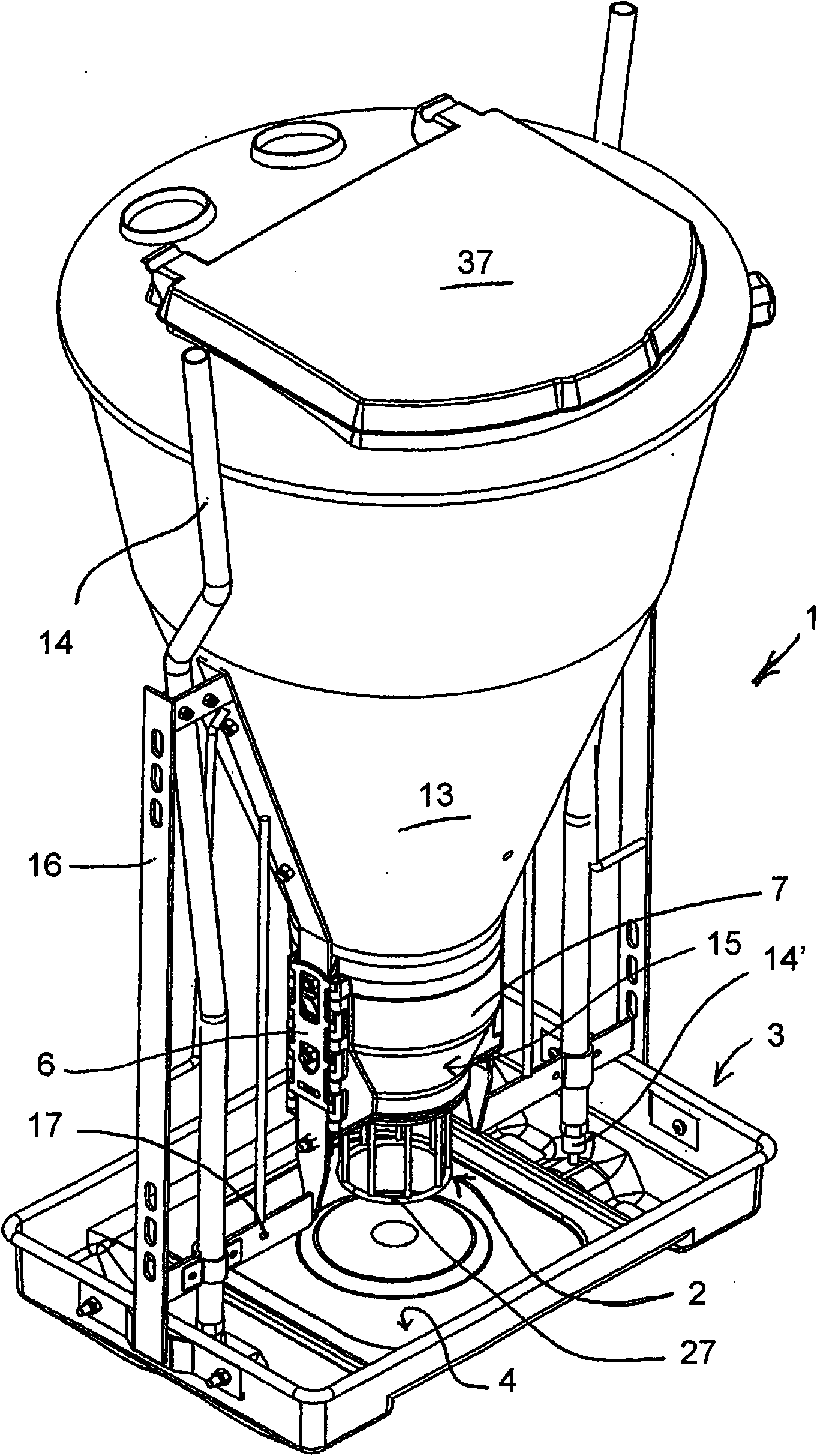
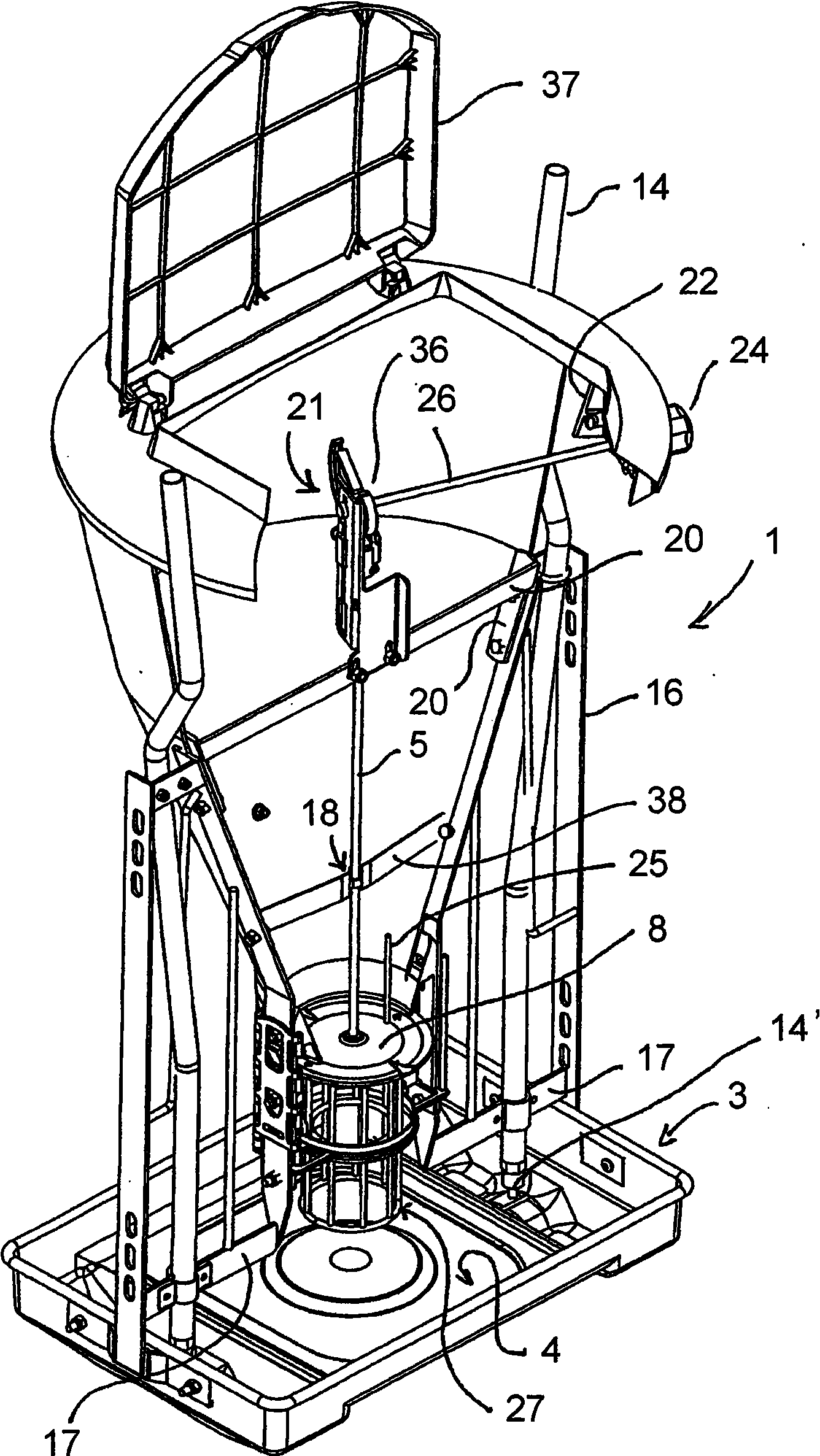
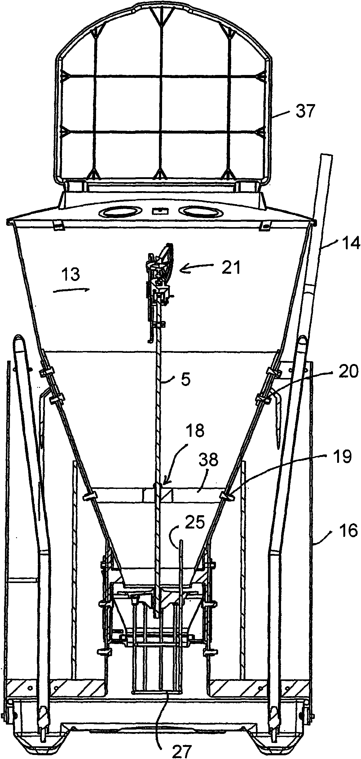
[0032] figure 1 and figure 2 A feed device 1 according to the invention is shown. The feeding device 1 comprises a feed container 13 and a dispenser unit 2 arranged below said container with a grate 27 arranged immediately above a base 3 designed as a belt There are 4 feed plates. Such as figure 2 As shown, the dispenser unit 2 is pivotally mounted on the lever 5 in a tubular duct 7 fastened to the fitting 6 . At the upper end of the dispenser unit 2 there is a disc-shaped element 8 whose edge 9 forms a gap 10 with the edge 11 of the outlet 12 of the feed container 13 . The disc-shaped element 8 has a slightly larger area than the outlet 12 of the feed container 13 and has a slightly upward edge 9 which reduces the speed at which feed, especially pelleted feed, leaves the feed container ...


PUM


Abstract

There is disclosed a feeding device (1) for feeding animals, preferably pigs. The feeding device (1) includes a feeding reservoir (13) and a movable dispensing unit (2) which by movement is adapted to release feed from the reservoir (13) for sprinkling down upon a feed plate (4). The dispensing unit includes a grate (27) disposed at level above the feed plate (4) such that it can be reached by the animals' noses for actuating the movable dispensing unit (2).

Description

technical field [0001] The present invention relates to a feeding device for feeding animals, preferably pigs, comprising a feed / feed container and a movable dispensing unit comprising a grate and arranged to release feed from the container by movement to For spilling onto feed / feed boards. Background technique [0002] International patent application WO 01 / 8705 discloses a feed device of the type mentioned at the outset. This feeding device is provided with a tubular movable distribution unit connected to a plate-shaped element arranged close to the mouth of the feeding container so as to prevent the feed from flowing out of the container unless the distribution unit is moved. The dispensing unit forms a tube at the bottom which is moved by the pig's snout when the pig eats. In practice, it has been the case that after some time in operation the feed would cake on or over the plate-shaped element and it would be difficult to leave the mouth of the container. A so-called...

Claims


Application Information

Patent Timeline
IPC IPC(8): A01K5/02
CPCA01K5/0241A01K5/0233
Inventor H·拉斯穆森
Owner ACO FUNKI
Learn More