Track rail and motion guide device with the track rail

A motion guidance and guide rail technology, applied in the direction of linear motion bearings, mechanical equipment, bearings, etc., can solve the problem of not being able to ensure the load contact surface, etc.

Active Publication Date: 2012-10-10
THK CO LTD
View PDF0 Cites 0 Cited by
  • Summary
  • Abstract
  • Description
  • Claims
  • Application Information

AI Technical Summary

Problems solved by technology

However, in the case of the guide rail 111 having a substantially rectangular cross section perpendicular to the longitudinal direction, as shown in the enlarged schematic diagram of FIG. When the ball 112 bears the load, it will not be possible to ensure the load contact surface between the ball 112 and the rolling groove 113 with the contact angle in the oblique direction, which is not desirable.

Method used


Image

  • Track rail and motion guide device with the track rail
  • Track rail and motion guide device with the track rail
  • Track rail and motion guide device with the track rail

Examples


Embodiment Construction

[0027] Hereinafter, preferred embodiments for carrying out the present invention will be described using the drawings. In addition, the following embodiments do not limit the technical means related to each claim, and also do not limit that all combinations of the features described in the embodiments are essential to the solution means of the invention.

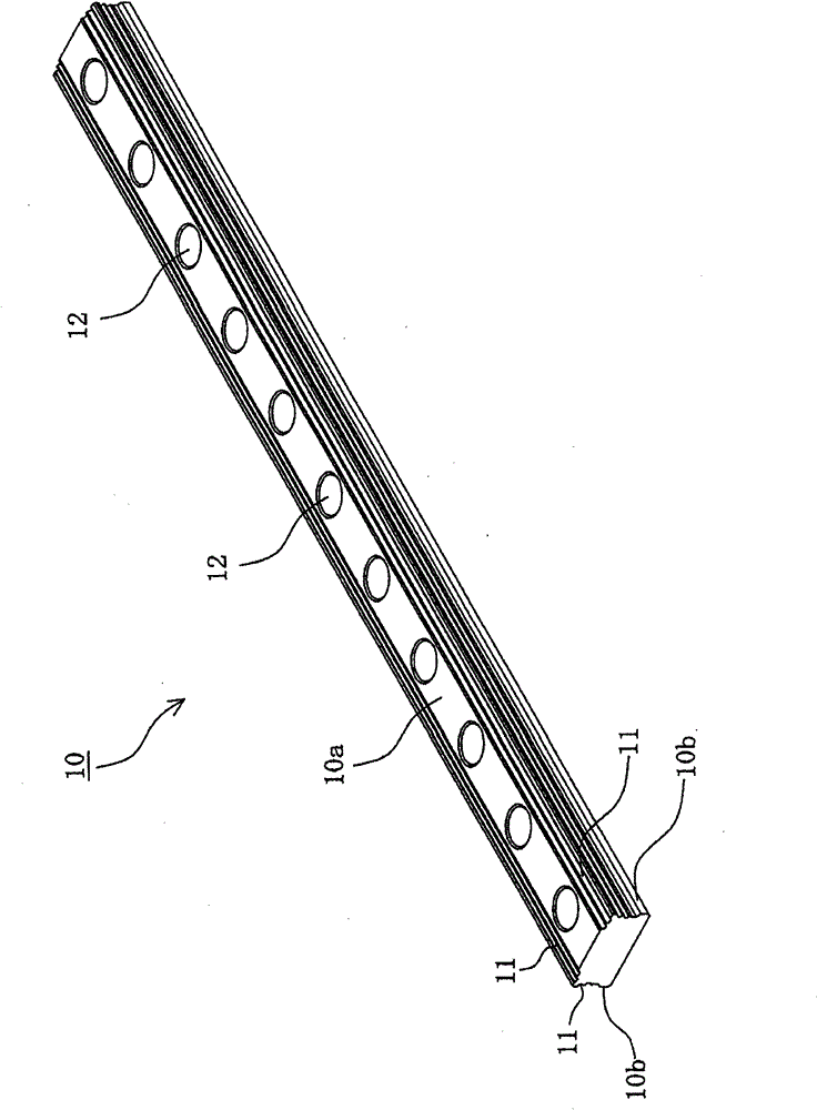
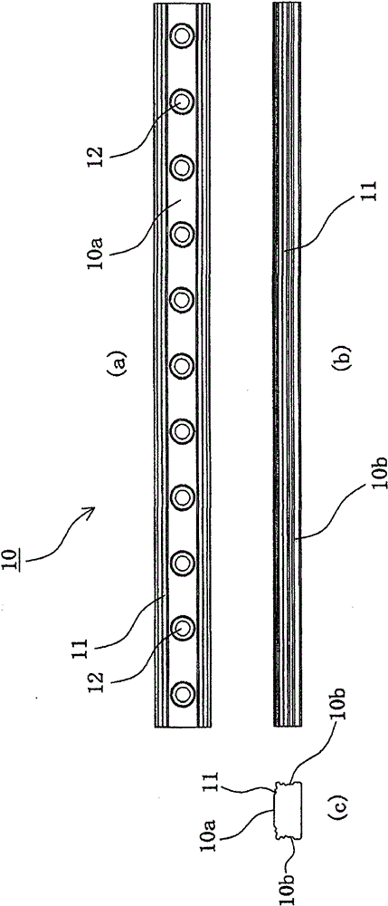
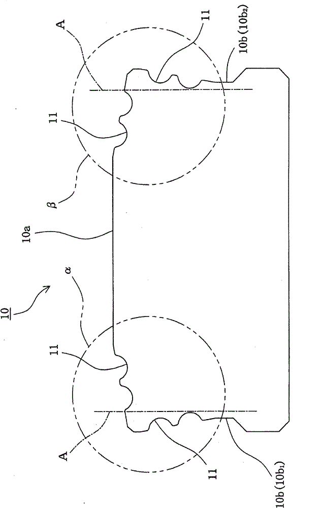
[0028] figure 1 It is an external perspective view of the guide rail according to this embodiment. and, figure 2 It is a figure for explaining the guide rail concerning this embodiment, figure 2 (a) is a top view, figure 2 (b) is a side view, figure 2 (c) Main view. in addition, image 3 It is a drawing which shows the characteristic front shape in the guide rail which concerns on this embodiment.

[0029] exist Figure 1 to Figure 3 The guide rail 10 according to the present embodiment shown in FIG. A plurality of unillustrated balls installed in a state of being assembled with an unillustrated moving block can...


PUM


Abstract

A motion guide device has high rigidity and high accuracy achieved by improving the shape of a track rail. The track rail (10) has at least two rolling body rolling grooves (11) in an upper face (10a) of the track rail and also has at least one rolling body rolling groove (11) in each of opposite side faces (10b) of the track rail, and all the rolling grooves (11) extend in the longitudinal direction of the track rail. When viewed in a cross section perpendicular to the longitudinal direction of the track rail (10), with two vertical imaginary lines (A, A) drawn from the edges on the oppositeouter sides of the at least two rolling grooves (11) formed in the upper face (10a), the at least one rolling groove (11) formed in each of the opposite side faces is located closer to a corresponding outer side face of the track rail than the imaginary line (A, A). Further, at least those portions of the track rail (10) which are near the rolling grooves (11) in both the upper face (10a) and theopposite side faces (10b) of the track rail (10) are formed with an inclination angle.

Description

technical field [0001] The present invention relates to an improved guide rail for increasing rigidity and high precision of a motion guide device, and a motion guide device provided with the guide rail. Background technique [0002] Conventionally, there is known a motion guide device that includes a guide rail and a moving block assembled to the guide rail via a plurality of rolling elements so that the moving block can relatively reciprocate along the longitudinal direction of the guide rail. [0003] As a representative form of the guide rail used in such a motion guide device, the guide rail shown in FIG. 7 and FIG. 8 is known. For example, in the case of the guide rail 101 shown in FIG. 7 , the rolling element rolling grooves 103 receiving the load from the balls 102 are formed at positions aligned in the vertical direction, and the head shape of the guide rail 101 is determined by the length of the guide rail 101 When viewed in a cross section perpendicular to the di...

Claims


Application Information

Patent Timeline
Patent Type & Authority Patents(China)
IPC IPC(8): F16C29/06
CPCF16C29/0647F16C33/58F16C29/005F16C29/0638F16C33/585
Inventor 岸弘幸森信也岛村武志
Owner THK CO LTD
Why Eureka
Try Eureka