Indoor machine for air conditioner

An air-conditioning device and an indoor unit technology, which is applied in the field of indoor units and can solve problems such as damaging the design of indoor units

Inactive Publication Date: 2010-08-11
DAIKIN IND LTD
View PDF1 Cites 4 Cited by
  • Summary
  • Abstract
  • Description
  • Claims
  • Application Information

AI Technical Summary

Problems solved by technology

However, in the case where the panel is rotated relative to the main body to open the suction port, it is necessary to increase the connecting gap (っなぎ目) between the panel and the main body so that the panel can be rotated without problems, so the design of the indoor unit is impaired. sex

Method used


Image

  • Indoor machine for air conditioner
  • Indoor machine for air conditioner
  • Indoor machine for air conditioner

Examples


no. 1 Embodiment approach

[0046] (1) Composition

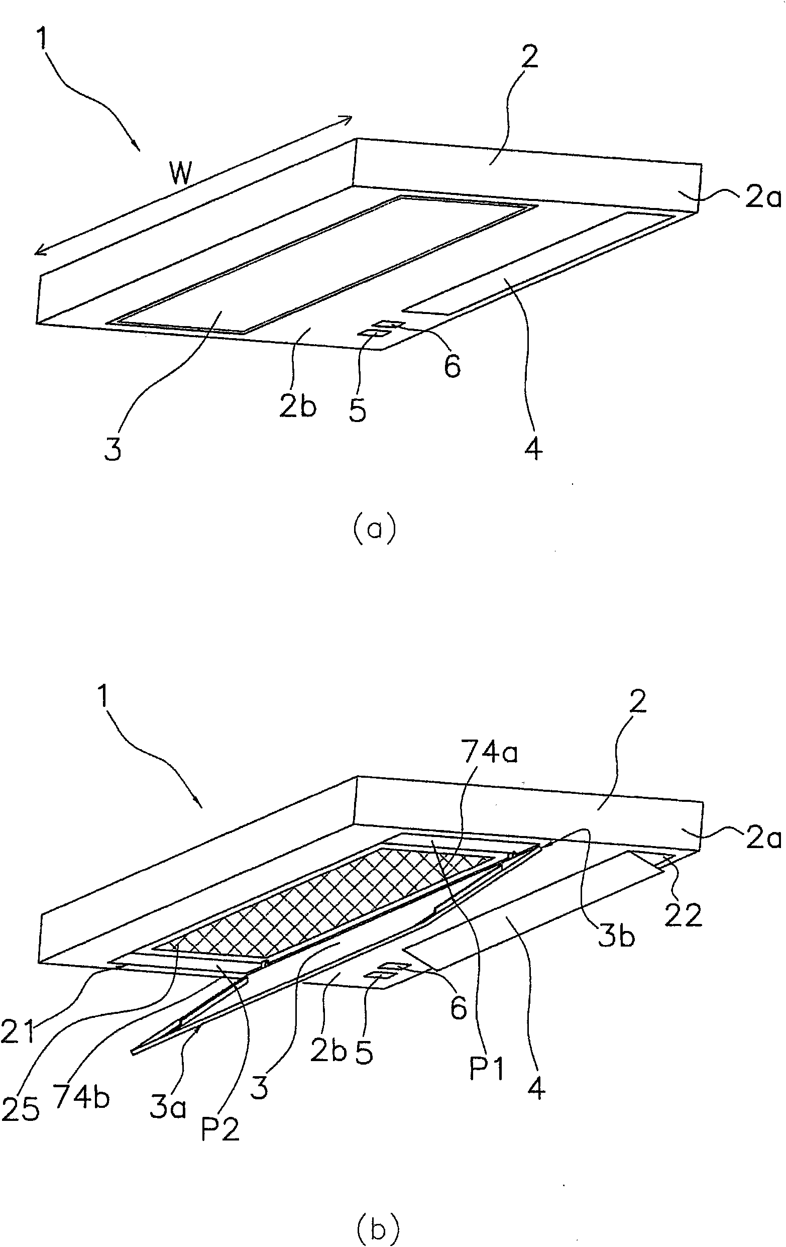
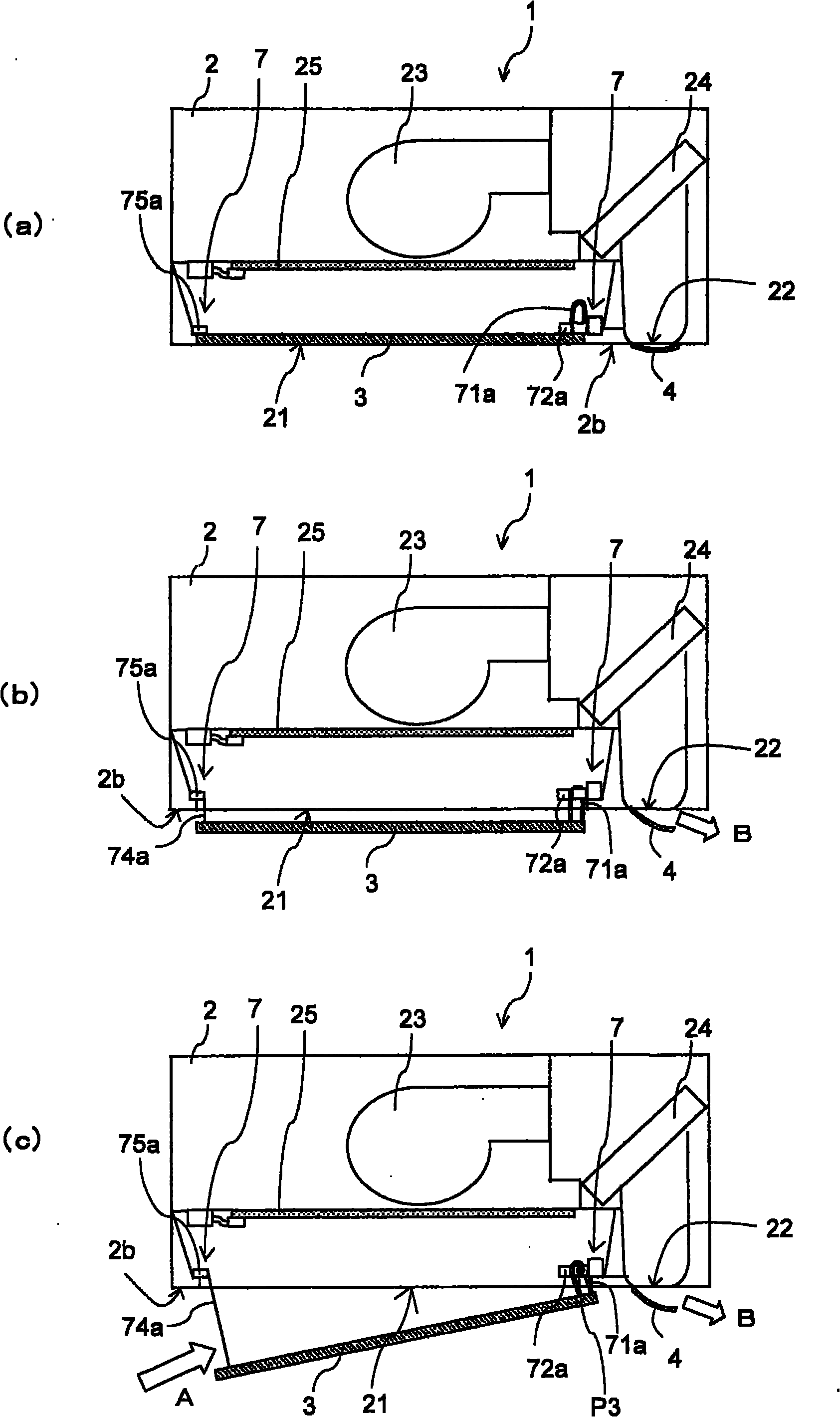
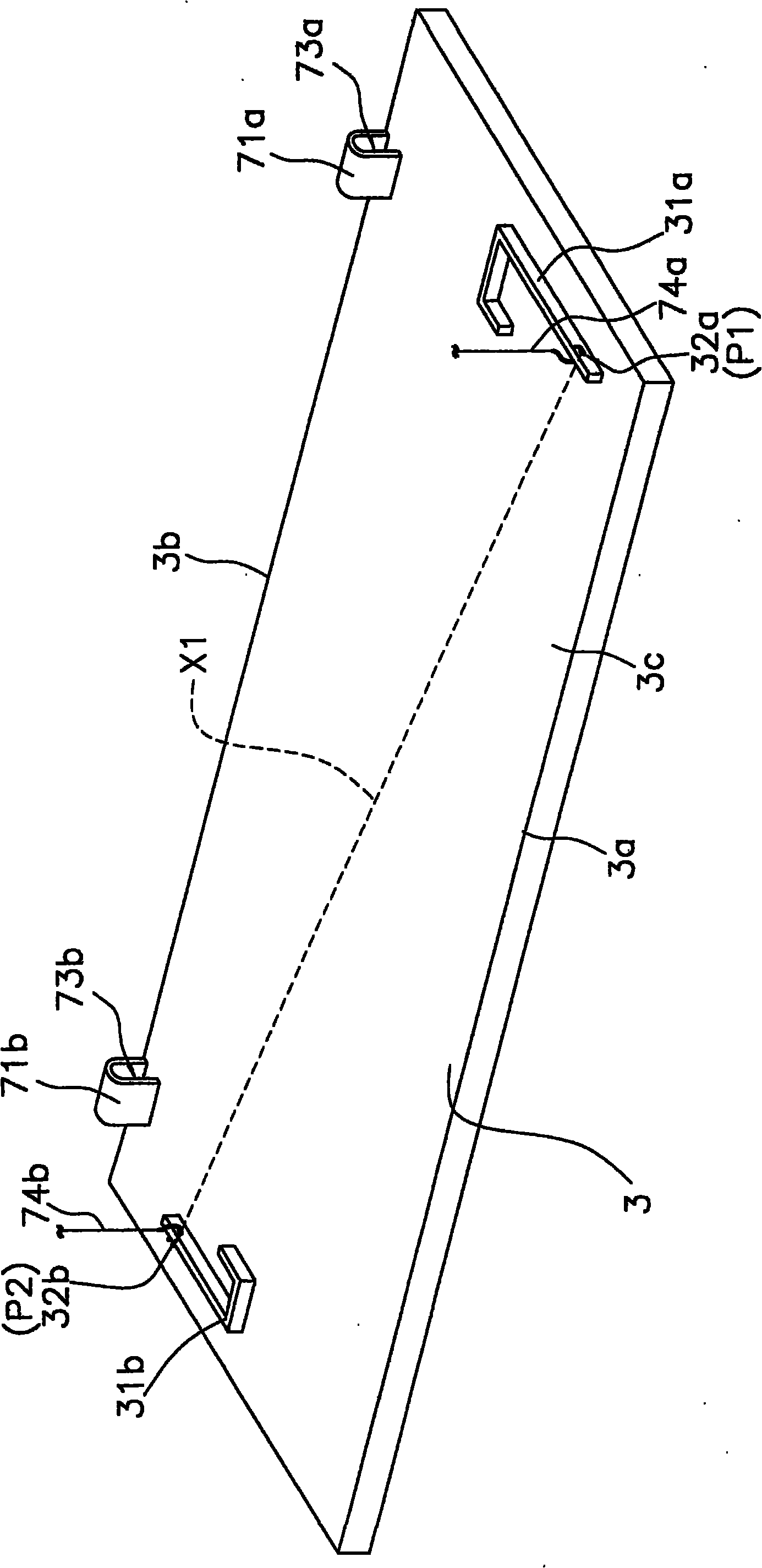
[0047] figure 1 (a) and (b) are perspective views of the indoor unit 1 of the air conditioner according to the present embodiment when the operation is stopped and when the operation is in operation, respectively. figure 2 (a) to (c) are viewed from the first side surface 2a side of the indoor unit 1 figure 1 A schematic diagram of the internal structure of the indoor unit 1. The indoor unit 1 is a so-called ceiling-mounted indoor unit installed on a ceiling indoors, and can perform heating operation, cooling operation, and the like.

[0048] Such as figure 1 , figure 2 and Figure 6 As shown, the indoor unit 1 has a main body 2 , a flat panel 3 (equivalent to a panel), a horizontal baffle 4 , a receiving part 5 , an operating state display part 6 , a panel driving part 7 and a control part 9 .

[0049] In addition, in the following, expressions such as "upper", "lower", "right", and "left" are used as appropriate, such as "below" of the main b...

no. 2 Embodiment approach

[0099] Next, use Figure 7 and Figure 8 The indoor unit 101 of the air conditioner according to the second embodiment of the present invention will be described. Figure 7 (a) to (c) are schematic diagrams showing the internal structure of the indoor unit 101 according to the second embodiment, Figure 8 It is a block diagram schematically showing each device constituting the indoor unit 101 .

[0100] (1) Composition

[0101] Similar to the first embodiment, the indoor unit 101 is an indoor unit of a ceiling-mounted air conditioner. The indoor unit 101 mainly includes: a main body 102 , a flat panel 103 , a horizontal baffle 104 , a receiving unit 105 , an operating state display unit 106 , a panel driving unit 107 and a control unit 109 . One air inlet 121 and one air outlet 122 are formed on the lower surface of the main body 102 , that is, the decorative panel 102 b , and the main body 102 houses a blower fan 123 , an indoor heat exchanger 124 , and a filter 125 . In...

no. 3 Embodiment approach

[0133] Next, use Figure 10 ~ Figure 13 The indoor unit 201 of the air conditioner according to the third embodiment of the present invention will be described. Figure 10 It is a perspective view of the indoor unit 201 in operation. Figure 11 (a) to (c) are viewed from the first side surface 202a side of the indoor unit 201 Figure 10 A schematic diagram of the internal structure of the indoor unit 201. Figure 12 is an enlarged view of the flat panel 203, Figure 13 It is a block diagram schematically showing each device constituting the indoor unit 201 .

[0134] (1) Composition

[0135]Similar to the first and second embodiments, the indoor unit 201 is an indoor unit of a ceiling-mounted air conditioner, and mainly includes a main body 202, a flat panel 203, a horizontal baffle 204, a receiving part 205, an operating state display part 206, and a panel drive. part 207 and the control part 209. One suction port 221 and one blowing port 222 are formed on the lower sur...


PUM


Abstract

An indoor unit for an air conditioner, in which a gap at a joint between a panel and a body is set small, so that aesthetic design of the indoor unit is not impaired. In the indoor unit (1) of a ceiling mounting air conditioner, an indoor air suction opening (21) is located at a decorative panel (2b) forming the lower surface of the body (2). The indoor unit (1) has a flat panel (3) and a panel drive section (7). The flat panel (3) can take a closed position for closing the suction opening (21) and an open position for opening the suction opening (21) by tilting relative to the closed position. When the flat panel (3) moves from the closed position to the open position, the panel drive part (7) operates the flat panel (3) so that the flat panel (3) pivots about a predetermined pivot point(P3) after descending to a predetermined position.

Description

technical field [0001] The present invention relates to an indoor unit of an air conditioner, and more particularly to an indoor unit of a ceiling-mounted air conditioner in which a suction port for indoor air is located on a lower surface of a main body. Background technique [0002] Conventionally, as an indoor unit of an air conditioner installed on a ceiling, for example, as disclosed in Patent Document 1, an indoor unit having an air outlet on the lower surface of a main body is widely known. In the indoor unit of Patent Document 1, a horizontal damper for changing the airflow direction of the air blown out from the air outlet is provided in the vicinity of the air outlet. Furthermore, in this indoor unit, the horizontal damper is rotated around two different points so as to extend the reach distance of blown air from the air outlet, thereby ensuring a sufficient volume of air blown out in the horizontal direction. [0003] Patent Document 1: Japanese Patent Laid-Open ...

Claims


Application Information

Patent Timeline
Patent Type & Authority Applications(China)
IPC IPC(8): F24F13/20F24F13/14F24F1/0047
CPCF24F2001/0037F24F13/20F24F1/0007F24F1/0047
Inventor 赤井竜彦水口康夫
Owner DAIKIN IND LTD
Why Eureka
Try Eureka