Delay management for distributed communications networks

A technology of communication network and network, applied in the field of delay management of distributed communication network, which can solve the problems of increased complexity and cost, increased complexity and/or cost of distributed antenna system, etc.

Inactive Publication Date: 2010-08-11
ADC TELECOMMUNICATIONS
View PDF2 Cites 18 Cited by
  • Summary
  • Abstract
  • Description
  • Claims
  • Application Information

AI Technical Summary

Problems solved by technology

Unfortunately, conventional techniques for establishing delays for the various remote units add considerable complexity and / or cost to distributed antenna systems
For example, some common network synchronization techniques involve the use of various positioning technologies (e.g., Global Positioning System or GPS) that add further complexity and cost to operating these distributed antenna systems reliably and efficiently

Method used


Image

  • Delay management for distributed communications networks
  • Delay management for distributed communications networks
  • Delay management for distributed communications networks

Examples


Embodiment Construction

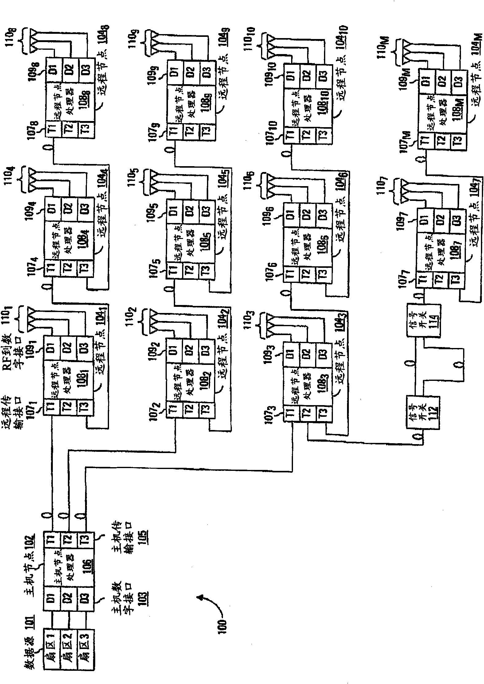
[0010] The detailed description that follows relates to delay management of a distributed communication network, such as a distributed antenna system. The delay management discussed here enables network administrators to establish desired delays at multiple nodes in a point-to-multipoint communication network with a suitably high degree of repeatability and control. The desired delay may be per node collectively or per individual node. Advantageously, the communication networks discussed herein use a distributed approach to determining signal path delays from the host to each node in the system. This is done at each node by discovering transmission delays (eg, propagation times) on the links between the node and its neighboring (eg, consecutive) nodes in the network. For example, each node learns the distance between itself and any downstream neighbors. Based on these transmission delays between nodes, the nodes in the system cooperate to determine the signal path delay of e...


PUM


Abstract

A method for programming the delay for a node in a communication system is disclosed. The node receives a selected delay value and a signal path delay value indicating a delay for signals communicated to the node. The signal path delay comprises an aggregation of transport delays calculated by each node for segments of the communication system between the node and a host node. The method further calculates an additional delay necessary to meet the selected delay value.

Description

Background technique [0001] Distributed antenna systems are widely used to seamlessly extend the coverage of wireless communication signals to locations not adequately served by traditional base stations, or to allocate capacity from a centralized radio suite. These systems generally include a host unit and a plurality of remote units. The master unit is typically coupled to a base station or between radio kits and multiple remote units. Each of the plurality of remote units includes one or more antennas that transmit and receive wireless signals on behalf of the base station or radio suite. [0002] A common problem in distributed antenna systems is to accommodate the different delays associated with each remote unit. Each remote unit is typically located at a different distance from the host. To allow the various antennas to be synchronized, a delay value is typically set at each remote unit. Unfortunately, conventional techniques for establishing delays for the various...

Claims


Application Information

Patent Timeline
Patent Type & Authority Applications(China)
IPC IPC(8): H04L12/56H04B7/26
CPCH04W48/08H04W28/18H04W24/00H04J3/0682
Inventor S·B·斯图尔特J·M·赫丁
Owner ADC TELECOMMUNICATIONS
Why Eureka
Try Eureka