Sagnac/Mach-Zehnder interferometer profile fiber sensing system and time domain positioning method thereof
A technology for distributing optical fibers and sensing systems, applied in pipeline systems, gas/liquid distribution and storage, mechanical equipment, etc., can solve the problems of high cost, complex signal demodulation, limited detection distance, leakage signal spectrum width, etc. The effect of long positioning distance and high positioning accuracy
Inactive Publication Date: 2010-08-25
SHANGHAI UNIV
View PDF3 Cites 17 Cited by
- Summary
- Abstract
- Description
- Claims
- Application Information
AI Technical Summary
Benefits of technology
This new technology uses an Optrode Interference Microscope (OMI) sensor that can be used for detection purposes while also being able to track changes over time without requiring external lights or equipment. It achieves this by measuring how well two different wavelength signals are mixed together when they pass through certain parts of their device called the microlens array. By analyzing these measurements it provides valuable insights into any issues affecting signal quality such as power supply failings or environmental factors like temperature fluctuations.
Problems solved by technology
This patented technical problem addressed in this patents relates to improving the accuracy and reliability of detecting leaks caused by oil/gas pipe lines during operations such as sewerage drainage works at public places like airports or military bases where large amounts of water can accumulate over time without being detected properly.
Method used
View moreImage
Smart ImageViewing Examples
Examples
Embodiment 1
Embodiment 2
Embodiment 3
Login to View More PUM
 Abstract
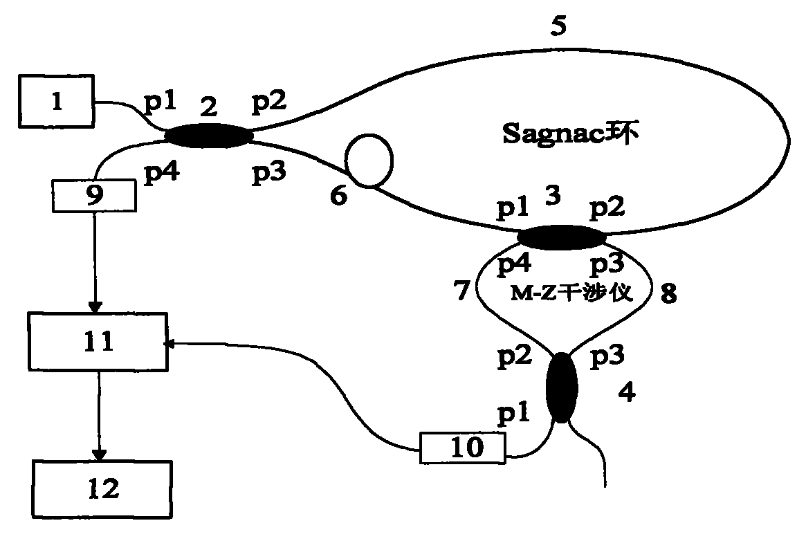
The invention discloses a Sagnac/Mach-Zehnder interferometer profile fiber sensing system and a time domain positioning method thereof. The system comprises a nested structure of a Sagnac interferometer consisting of three fiber couplers and four fibers and a Mach-Zehnder interferometer, wherein the Sagnac/Mach-Zehnder interferometers are respectively connected with an incoherent light source and two photoelectric detectors. In the time domain correlation positioning method, the cross-correlation operation of disturbing signals detected by the Sagnac interferometer and the Mach-Zehnder interferometer are utilized to determine the time used from disturbance propagation to one end of a sensing fiber, the delay time of a maximum value point of a cross-correlation curve corresponds to the time, and a disturbance position is determined by using the time. The invention overcomes the defects of limit positioning distance and positioning precision of a traditional Sagnac nterferometer profile fiber sensing system.
Description
Login to View More Claims
Login to View More Application Information
Patent Timeline
 Owner SHANGHAI UNIV
Features
- R&D
- Intellectual Property
- Life Sciences
- Materials
- Tech Scout
- Unparalleled Data Quality
- Higher Quality Content
- 60% Fewer Hallucinations
Learn More Browse by: Latest US Patents, China's latest patents, Technical Efficacy Thesaurus, Application Domain, Technology Topic, Popular Technical Reports.
© 2025 PatSnap. All rights reserved.Legal|Privacy policy|Modern Slavery Act Transparency Statement|Sitemap|About US| Contact US: help@patsnap.com


