Liquid conveyer used between storage tanks

A technology of conveying device and storage tank, applied in gas/liquid distribution and storage, pipeline system, mechanical equipment, etc., can solve the problems of chemical product impact, impurity entry, impact on product quality, etc., to ensure normal use and product quality. , the effect of simple structure

Inactive Publication Date: 2010-09-01
JURONG NINGWU CHEM
View PDF0 Cites 3 Cited by
  • Summary
  • Abstract
  • Description
  • Claims
  • Application Information

AI Technical Summary

Problems solved by technology

The disadvantage of this transmission method is: since the air inlet 15 and the air outlet 16 are open, there will be impurities entering the storage tank, which will affect the quality of the product; Contains humidity and gas impurities, which will still affect some special chemical products in the storage tank

Method used


Image

  • Liquid conveyer used between storage tanks
  • Liquid conveyer used between storage tanks
  • Liquid conveyer used between storage tanks

Examples


Embodiment Construction

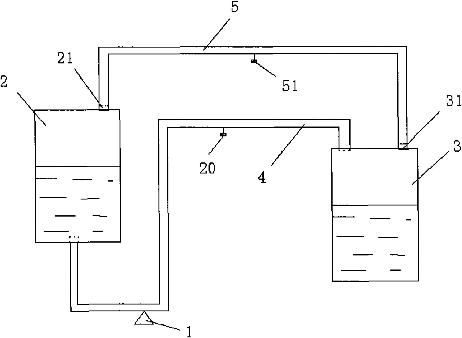
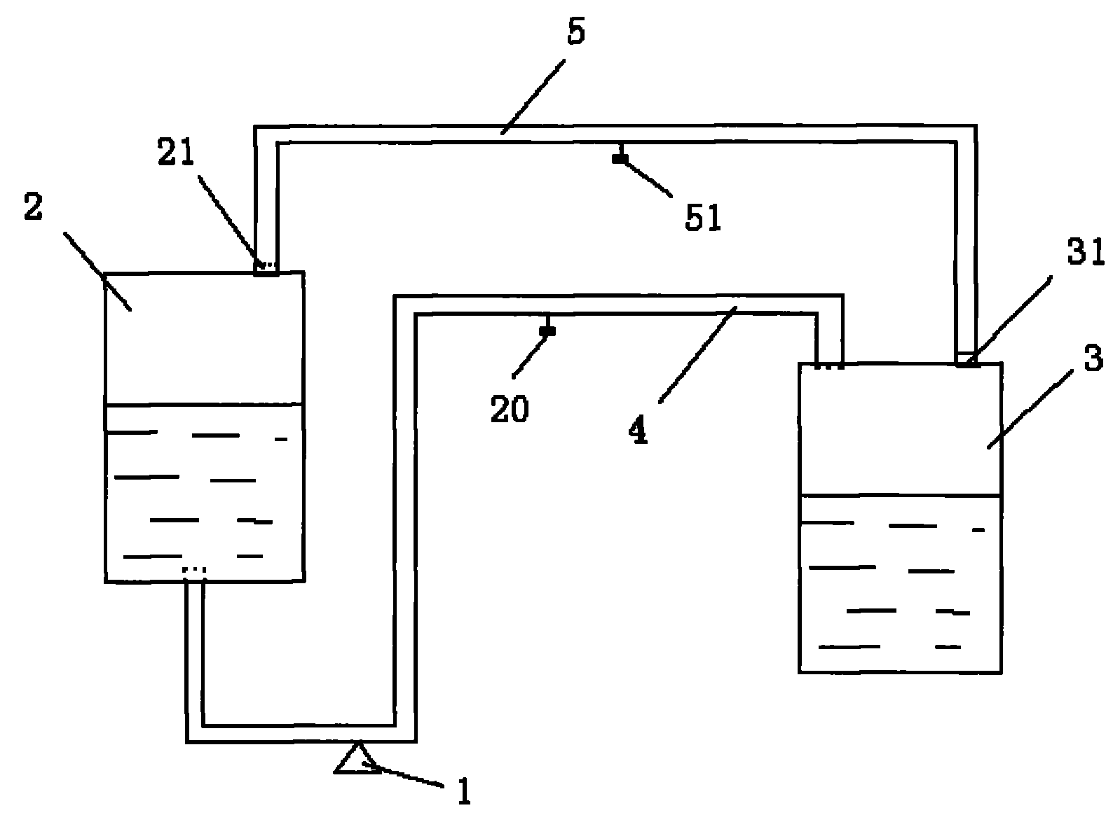
[0011] A kind of liquid transmission device used between storage tanks according to the present invention, see figure 2 , the liquid transmission device used between the storage tanks includes an extraction pump 1, an output storage tank 2, an input storage tank 3 and a pipeline 4, the extraction pump 1 is arranged on the pipeline 4, and one end of the pipeline 4 is located at the bottom of the output storage tank 2 , the other end is located at the top of the input storage tank 3. The top of the output storage tank 2 is provided with an air inlet 21 , and the top of the input storage tank 3 is provided with an air outlet 31 , and the air inlet 21 and the air outlet 31 are connected through a gas balance pipe 5 .

[0012] For ease of use, a balance control valve 51 is provided on the gas balance pipe 5 . A control valve 20 is provided on the line 4 .

[0013] When in use, the extraction pump 1 is turned on, and the liquid in the output storage tank 2 is transferred to the i...


PUM


Abstract

The invention discloses a liquid conveyer used between storage tanks, which comprises an extraction pump, an output storage tank, an input storage tank and a pipeline, wherein the extraction pump is arranged on the pipeline; the top of the output storage tank is provided with an air inlet; the top of the input storage tank is provided with an air outlet; and the air inlet and the air outlet are connected with each other through an air balancing pipe. The liquid conveyer has a simple structure and a novel mode, makes no impurities enter the storage tanks, ensure the product quality, and can keep the pressure between the two storage tanks to be always in a balanced state to ensure the smooth conveying of liquids.

Description

technical field [0001] The present invention relates to a liquid transfer device, in particular to a liquid transfer device used between storage tanks. Background technique [0002] In production, it is often necessary to transfer the liquid in one storage tank to another storage tank, and realize liquid transfer in multiple storage tanks. During the liquid transfer process in the storage tank, on the one hand, as the liquid in the output storage tank decreases, the gas pressure will become smaller and smaller. In order to ensure the pressure in the storage tank, it is necessary to input gas into the storage tank; on the other hand, the input As the liquid in the storage tank increases, the gas pressure will increase. In order to ensure the normal transmission of liquid to the storage tank, the gas in the storage tank needs to be discharged. The existing liquid transmission methods between storage tanks are shown in figure 1 . The output storage tank 12 is connected with t...

Claims


Application Information

Patent Timeline
Patent Type & Authority Applications(China)
IPC IPC(8): F17D1/14
Inventor 应珏应军翟洪金陈云良
Owner JURONG NINGWU CHEM
Why Eureka
Try Eureka