Separation-type switching control electric connector

A technology for conversion control and electrical connectors, which is applied to devices and circuits for connecting, joining/disconnecting connected parts, etc. It can solve the problems of occupying a large internal space of equipment, does not have conversion test, cannot be repeatedly plugged and unplugged, and achieves production The effect of low cost, compact structure and simple design

Active Publication Date: 2011-08-24
CHINA NORTH IND GRP HANGLIAN TECH CO LTD
View PDF0 Cites 0 Cited by
  • Summary
  • Abstract
  • Description
  • Claims
  • Application Information

AI Technical Summary

Problems solved by technology

[0003] In order to solve the problem that the internal electrical connectors of important equipment in the prior art cannot be repeatedly plugged and unplugged after they are installed in place, and do not have functions such as conversion testing and actual combat, the electrical signals are seat-in and head-out, and multiple electrical paths for electrical connections are installed inside the equipment. To meet the requirements of various tests and actual combat, the structure is cumbersome, takes up a large internal space of the equipment, and has high production costs. The signal is seat-in and seat-out, and the switching plug can be conveniently and quickly plugged and unplugged outside the equipment, which meets the electrical path of important equipment testing and actual combat requirements

Method used


Image

  • Separation-type switching control electric connector
  • Separation-type switching control electric connector
  • Separation-type switching control electric connector

Examples


Embodiment Construction

[0017] The present invention will be further described below in conjunction with the accompanying drawings and specific embodiments.

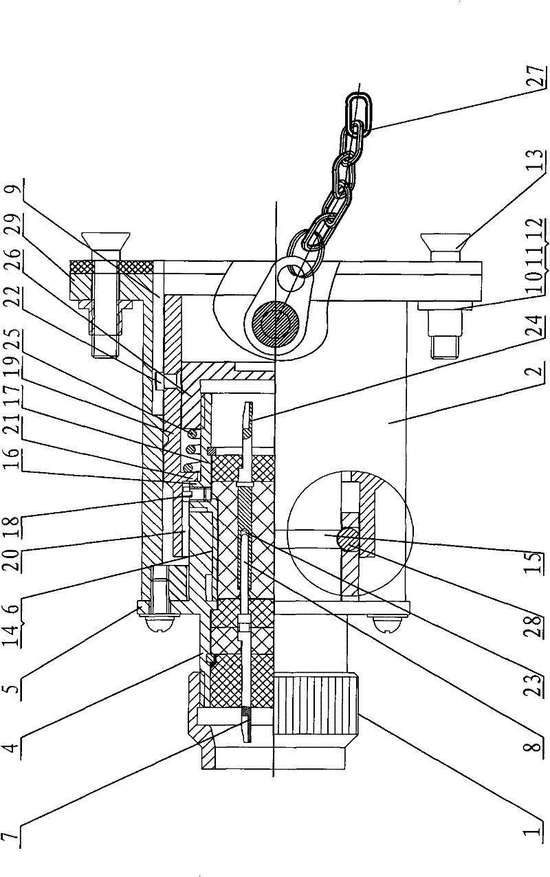
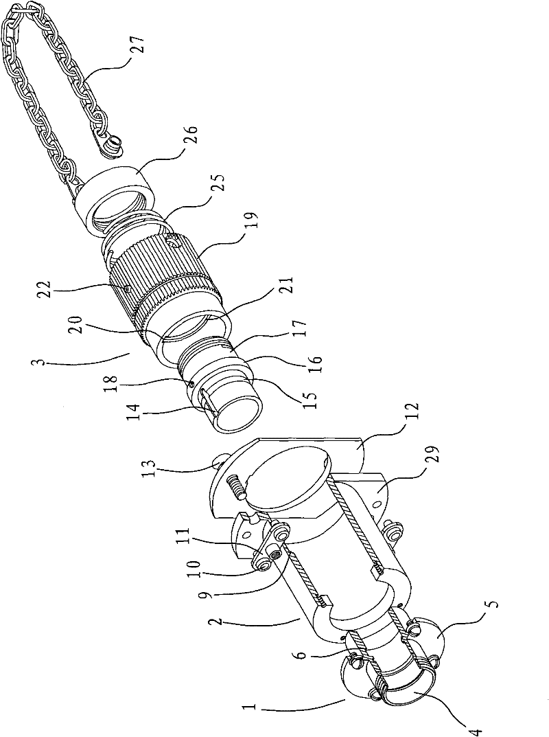
[0018] figure 1 , 2 . The detachable conversion control electrical connector shown in 3 mainly includes a socket 1 , a fixing sleeve 2 , and an adapter plug 3 . The wall of the mating end of the seat housing 4 of the socket 1 is provided with a locking pin 28 placed in the hole, and the inner edge of the mating end of the seat housing 4 is provided with a convex key 6 in the axial direction, and the mating end of the socket 1 Placed in the inner cavity of one end of the fixed sleeve 2, the flange plate 5 on the seat shell of the socket is locked and connected with the end face of the fixed sleeve 2 through bolts; the other end of the fixed sleeve 2 is the installation end, and the installation end is provided with a flange 29, and the installation end The two ends on the inner side of the flange are respectively fixed and locked by the bracke...


PUM


Abstract

The invention relates to a separation-type switching control electric connector which is composed of an adapter plug, a socket and a fixed sleeve, wherein the socket is fixedly connected with one end of the fixed sleeve by a flange disk on a base case of the socket; the adapter plug is arranged in the inner chamber of the mounting end of the fixed sleeve and is in plug-in or separation state withthe socket in the inner chamber of the fixed sleeve; one end of the socket is connected with a signal input end and a signal output end, and the other end of the socket is connected with the adapter plug which is a test plug or an actual combat plug; and the test plug or the actual combat plug is respectively plugged with the socket to ensure that the signal input end and the signal output end ofa socket signal are communicated with and outputs the test signal or the actual combat signal. The signal of the electric connector is input and output from the socket, is respectively connected withthe socket by a plurality of adapter plugs to realize multifunctional switching without providing respective electric passages for each function, satisfies the installation requirements of high precision and small space of the internal devices of special equipment, and has compact structure and convenient and quick switch of plugging and unplugging.

Description

technical field [0001] The invention relates to an electrical connector, in particular to an electrical connector used for testing and actual combat of important equipment. Background technique [0002] At present, the widely used electrical connectors are generally one head and one head, and the electrical signal is input from the socket and output from the plug. For some electrical devices with high manufacturing costs and high precision requirements, especially electrical connectors installed inside important equipment, one mating corresponds to a fixed pattern of electrical pathways, which does not have the function of repeated plugging and unplugging. Once the internal installation is in place, it cannot be inspected and maintained. Once a fault occurs, it will be very difficult to maintain and replace, which will affect the stability of the equipment and cannot meet various requirements such as testing and actual combat of the equipment. It needs to take up more space...

Claims


Application Information

Patent Timeline
Patent Type & Authority Patents(China)
IPC IPC(8): H01R31/00H01R31/06H01R13/52H01R13/62
Inventor 叶学俊蒋绍臣卢春兰常妍徐继华
Owner CHINA NORTH IND GRP HANGLIAN TECH CO LTD
Why Eureka
Try Eureka