Sensor node positioning method

A sensor node and positioning method technology, applied in electrical components, wireless communication, network topology and other directions, can solve the problems of high computational resource consumption of nodes to be located, algorithms falling into local optimal solutions, low node positioning accuracy, etc. The effect of resource consumption, increased speed, and reduced burden

Inactive Publication Date: 2012-05-30
UNIV OF SCI & TECH OF CHINA
View PDF0 Cites 0 Cited by
  • Summary
  • Abstract
  • Description
  • Claims
  • Application Information

AI Technical Summary

Problems solved by technology

Some positioning algorithms currently proposed, such as maximum likelihood estimation method (MLE), no-search quasi-Newton method (MNSQN), no-search steepest descent method (NSSD), etc., all run the positioning algorithm on the node S to be located, and the consumption is to be determined The computing resources of the bit node are also very strict on the initial value of the optimization
[0003] In addition, particle swarm optimization algorithms have been proposed in the application of sensor node positioning, but these algorithms have obvious disadvantages: they are centralized algorithms, and the computing resources of the nodes to be positioned are very high.
In addition, these algorithms adopt a single-population strategy, which easily makes the algorithm fall into a local optimal solution.
Therefore, the accuracy with respect to node localization is not high

Method used


Image

  • Sensor node positioning method
  • Sensor node positioning method
  • Sensor node positioning method

Examples


Embodiment 1

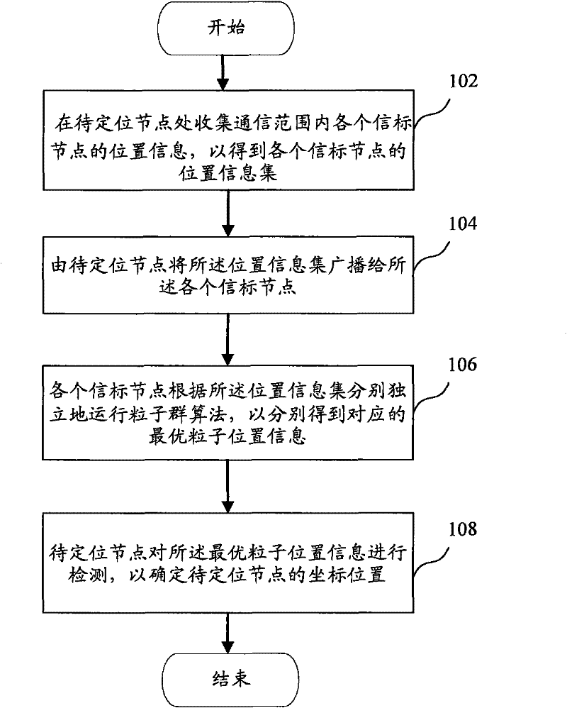
[0043] Embodiment 1: After receiving the coordinates of the optimal particles of all beacon nodes, the node to be positioned calculates the corresponding optimal particle position information of each beacon node according to the optimal particle position information and the evaluation function F. F value.

[0044] Then, find out all the particles satisfying F<ε. The threshold ε can be selected according to actual conditions, such as experimental results, and the threshold ε is generally selected to be between 10 and 30.

[0045] Finally, take the coordinate average of the selected optimal particle position information as the coordinate position of the node to be located. In one embodiment, the position of the node to be positioned is obtained by the following formula:

[0046] x = Σ i = ...

Embodiment 2

[0048] Embodiment 2: After receiving the coordinates of the optimal particles of all beacon nodes, the node to be positioned calculates the corresponding optimal particle position information of each beacon node according to the optimal particle position information and the evaluation function F. F value. Then, select the minimum value of F value corresponding to each optimal particle position information as the coordinate position of the node to be located. That is, use the particle coordinates with the smallest F value as the coordinates of the nodes to be located.

[0049] From the experimental data, it can be concluded that compared to using the particle coordinate position with the smallest F value as the position of the node to be located in the embodiment 2, the average value of these particle coordinate positions used in the embodiment 1 will be more accurate.

[0050] In step 106, each beacon node corresponds to the obtained phased global optimal particles, and there...


PUM


Abstract

The invention discloses a sensor node positioning method. The method comprises the following steps of: collecting the position information of each beacon node in a communication range at the node to be positioned to obtain the positioning information set of each beacon node; broadcasting the position information set to each beacon node by the node to be positioned; respectively independently operating a particle group algorithm by each beacon node according to the position information set to respectively obtain the corresponding the optimum particle position information; detecting the optimumparticle position information by the node to be positioned to fix the coordinate position of the node to be positioned. The invention can obviously reduce the calculation consumption of the node to be positioned.

Description

technical field [0001] The invention belongs to the technical field of wireless sensor network, distributed and evolutionary computing intersecting, and in particular relates to a sensor node positioning method. Background technique [0002] With the application of sensors more and more widely, how to quickly and accurately locate sensor nodes becomes more and more important. Some positioning algorithms currently proposed, such as maximum likelihood estimation method (MLE), no-search quasi-Newton method (MNSQN), no-search steepest descent method (NSSD), etc., all run the positioning algorithm on the node S to be located, and the consumption is to be determined At the same time, the computing resources of bit nodes have strict requirements on the initial value of optimization. [0003] In addition, particle swarm optimization algorithms have been proposed in the application of sensor node positioning at present, but these algorithms have obvious shortcomings: they are centra...

Claims


Application Information

Patent Timeline
Patent Type & Authority Patents(China)
IPC IPC(8): H04W64/00H04W84/18
Inventor 王行甫曹仁之钱雷熊焰
Owner UNIV OF SCI & TECH OF CHINA
Why Eureka
Try Eureka