
Wireless positioning method and apparatus

A wireless positioning and point location technology, applied in the field of communication, can solve the problems of real-time positioning calculation, high cost, and difficult calculation, and achieve the effect of reducing computing resource consumption and time cost.

Active Publication Date: 2017-12-12
BEIJING ABLOOMY TECH CO LTD
View PDF5 Cites 0 Cited by
  • Summary
  • Abstract
  • Description
  • Claims
  • Application Information

AI Technical Summary

Problems solved by technology

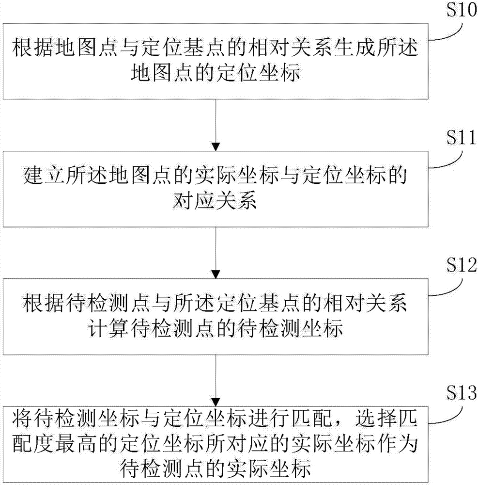
[0006] In the existing Wi-Fi positioning technology, when the wireless spectrum environment of the environment changes, it is necessary to repeat the on-site survey to ensure the positioning accuracy, and the cost is relatively high; other methods include using the terminal signal strength to calculate the distance, or using the signal transmission time difference However, due to the difficulty of calculation, it is impossible to complete large-scale real-time positioning calculations in embedded systems with limited computing resources.

Method used


Image

  • Wireless positioning method and apparatus
  • Wireless positioning method and apparatus
  • Wireless positioning method and apparatus

Examples


no. 1 example

[0061] The first embodiment describes the coordinate system of the present invention in a two-dimensional plan view.

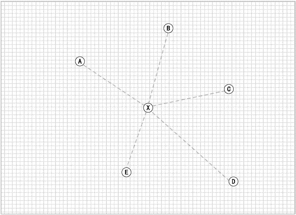
[0062] figure 2 is a schematic diagram of a wireless positioning method applied to a two-dimensional scene according to an embodiment of the present invention.

[0063] like image 3 As shown, if the size of the map and the positions of the positioning base points A, B, C, D, and E are known, these known base points can be used to accurately describe the positioning coordinates of the position X, such as the ratio of the distance from X to different base points. Define the positioning coordinates of X as {(D AX / D BX ), (D AX / D CX ), (D AX / D DX ), (D AX / D EX )}, where D mn Indicates the distance between two positions m and n, such as D AX Indicates the distance between location A and location X, D BX Indicates the distance between position B and position X. Map ( figure 1 The dotted grid in represents the range of the map, and the intersectio...

no. 2 example

[0069] In the second embodiment, the coordinate system in the three-dimensional space diagram of the present invention is described.

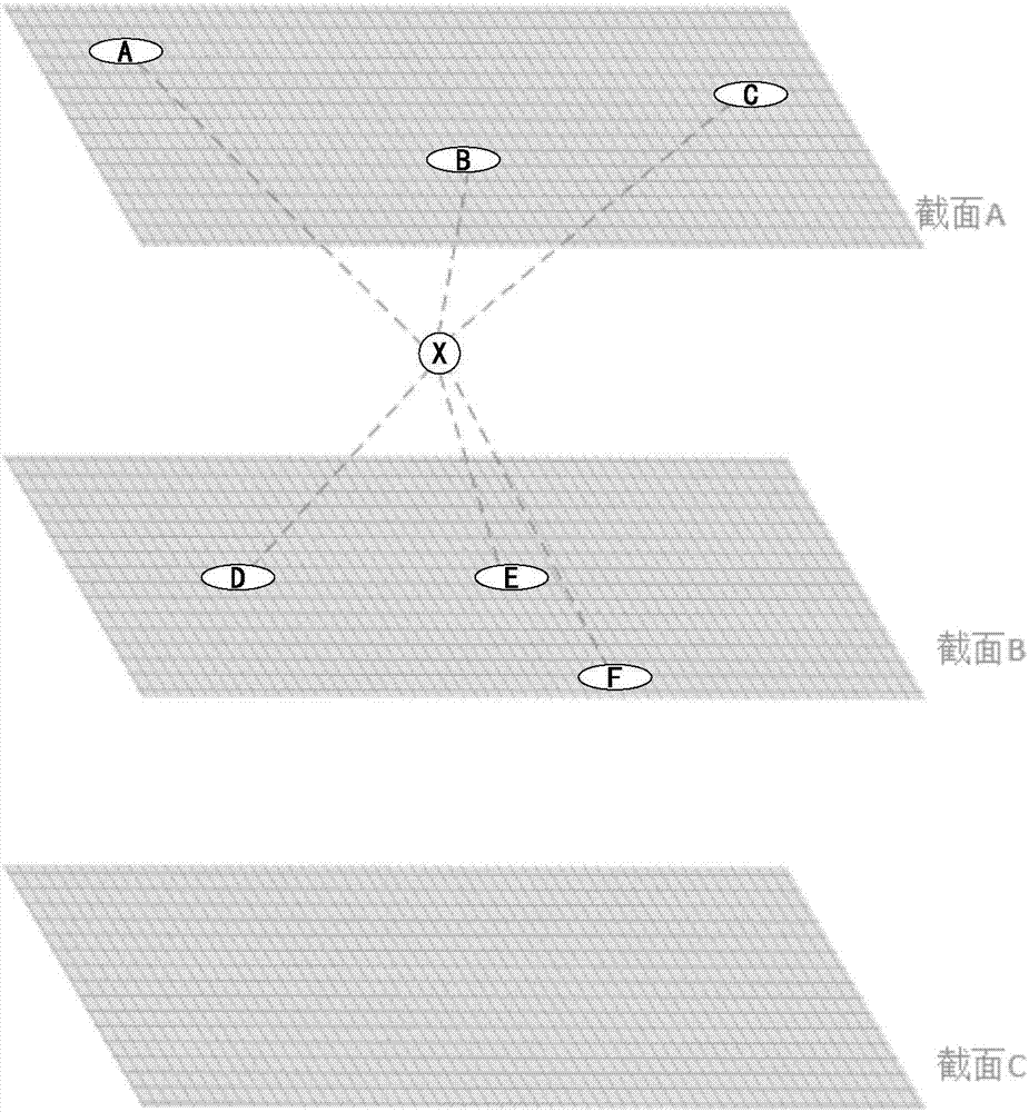
[0070] image 3 is a schematic diagram of a wireless positioning method applied to a three-dimensional scene according to an embodiment of the present invention.

[0071] in such as image 3 In the three-dimensional space shown, positioning base points are deployed on different sections (sections A, B, C), such as A, B, C, D, E, F and so on. Using the coordinate definition method for the position in the two-dimensional plane, the coordinate system in the three-dimensional space is described as formula 2:

[0072]

[0073] The left side of Equation 2 is the coordinate matrix of the actual coordinates of the map point, and the right side of the equation is the coordinate description matrix of the location coordinates of the map point.

[0074] The positioning method in the three-dimensional space is completely consistent with the two-dimens...


PUM


Abstract

The invention, which relates to the technical field of communication, discloses a wireless positioning method and apparatus. According to one embodiment, the method comprises: a positioning device is deployed in a regional map as a positioning base point and positioning coordinates of the regional map are generated according to a physical relationship between a to-be-localized device and the positioning device; a to-be-detected coordinate of a to-be-detected point is calculated based on a relative relationship between the to-be-detected point and the positioning base point; and the to-be-detected coordinate is matched with the positioning coordinates and an actual coordinate corresponding to the positioning coordinate with the highest matching degree is selected as an actual coordinate of the to-be-detected point. Therefore, the cost of early-stage positioning preparation is lowered; and the calculation difficulty during positioning is reduced.

Description

technical field [0001] The present invention relates to the field of communication technology, in particular to a method and device for wireless positioning. Background technique [0002] With the continuous development of data services and multimedia services, people's demand for positioning and navigation is increasing, especially in complex indoor environments, such as airport halls, exhibition halls, warehouses, supermarkets, libraries, underground parking lots, etc., often need The indoor location information of the mobile terminal or its holder is determined. [0003] Limited by the penetration of satellite signals, the satellite positioning system used in outdoor positioning is difficult to solve some positioning problems in indoor environments. Therefore, indoor positioning technology needs to rely on signal sources existing in specific environments for positioning. Existing indoor positioning technologies include A-GPS positioning technology, ultrasonic positioning...

Claims


Application Information

Patent Timeline
IPC IPC(8): G01S5/02G01S5/06
CPCG01S5/0252G01S5/06
Inventor 欧中云王凯沈文仕
Owner BEIJING ABLOOMY TECH CO LTD
Learn More