Intraocular tension testing device

A detection device and intraocular pressure technology, applied in the direction of tonometer, etc., can solve the problems of delayed early diagnosis, expensive, time-consuming and energy-consuming, etc., meet the requirements of accurate measurement, prevent vision degradation, and facilitate measurement

Inactive Publication Date: 2010-09-08
HUAZHONG UNIV OF SCI & TECH
View PDF0 Cites 10 Cited by
  • Summary
  • Abstract
  • Description
  • Claims
  • Application Information

AI Technical Summary

Problems solved by technology

[0005] Due to the existing intraocular pressure detection instrument 1, the operation is complicated and expensive, and it needs to be completed by a professional ophthalmologist for the patient; 2, it can only be measured once, and the patient needs to go to the hospital to measure the intraocular pressure from time to time, which consumes time and energy; 3. The intraocular pressure has a 24-hour fluctuation. Generally, the peak of intraocular pressure is at 5:30 in the morning, that is, the subjects with normal intraocular pressure during working hours have a peak of intraocular pressure that exceeds the normal range at night, and this peak of intraocular pressure occurs at 5:30 in the morning. Glaucoma patients are misdiagnosed as having normal intraocular pressure due to difficulty being detected during hospital working hours
Therefore, although a single intraocular pressure measurement is helpful for the diagnosis of glaucoma, it cannot fully understand the patient's intraocular pressure fluctuations throughout the day, delaying early diagnosis and missing the best treatment time

Method used


Image

  • Intraocular tension testing device
  • Intraocular tension testing device
  • Intraocular tension testing device

Examples


Embodiment Construction

[0023] Below in conjunction with accompanying drawing and example the present invention is described in further detail.

[0024] combine Figure 1 to Figure 4 The specific structure of the intraocular pressure detection device of the present invention will be further described in detail.

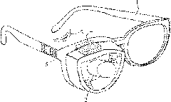
[0025] figure 1 For the overall structure of the present invention, the intraocular pressure detection device included in the present invention is specifically composed of two parts, namely the contact lens 3 and the bracket 1 . The contact lens 3 is embedded with an inner magnetic sheet 3 a, and the bracket 1 includes an outer magnetic sheet movement and detection device 2 , a signal processing unit 4 and a display storage part 5 .

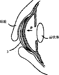
[0026] For the specific structure of contact lens 3, see figure 2 , whose shape and material are similar to ordinary contact lenses. The inner magnetic sheet 3a embedded inside is directly made into a ring with a soft magnetic material, or is customized wi...


PUM


Abstract

The invention discloses an intraocular tension testing method and an intraocular tension testing device based on a magnetic interaction. The method comprises the following steps: (1) wearing a corneal contact lens embedded with an inner magnetic disk to make the inner magnetic disk closely contact with the corneas; (2) placing another outer magnetic disk in front of the eyes perpendicular to the inner magnetic disk to make the two magnetic disks form a mutually repulsion force field; and (3) with the movement of the outer magnetic disk, picking up a repulsive force curve by a pressure sensor, and calculating the intraocular tension value through the inflexion point or the slope change of the curve. In the technical scheme of the invention, the outer magnetic disk is driven to move forward or backward by a built-in straight-line motion mechanism to adjust the repulsive force between the outer magnetic disk and the inner magnetic disk so as to realizing pressure application without contacting, and the measuring head can not directly contact with the eyeballs, thereby causing no pain; the invention does not require the testing of a doctor, the patient can operate individually, and the device can automatically calculate and store the measured intraocular tension value. When the invention is used, the intraocular tension can be tested by the method of calculating and obtaining the intraocular tension value through the curve of the repulsive force between the inner magnetic disk in the corneal contact lens and the moving outer magnetic disk, and the testing result can be accurate and reliable by performing the intraocular tension testing for five times and taking the average value.

Description

technical field [0001] The invention relates to a non-destructive detection technology of intraocular pressure, in particular to a continuous measurement device for intraocular pressure based on magnetic interaction, which belongs to the combination of non-destructive detection and medicine. Background technique [0002] Glaucoma is one of the main causes of blindness in my country and the second leading cause of blindness in the world (see editors-in-chief Zhao Kanxing and Yang Peizeng [M]. Ophthalmology. Beijing: People's Health Publishing House, 2008, 315). Glaucoma is characterized by pathological elevated intraocular pressure, irreversible optic atrophy, and visual field defect, which seriously affect the quality of life of patients. In my country, the incidence rate is 0.21%-1.64%, and the blindness rate is 10%-20%. It is one of the main diseases that endanger the health of middle-aged and elderly people (55-70 years old). The most common and effective way to prevent ...

Claims


Application Information

Patent Timeline
Patent Type & Authority Applications(China)
IPC IPC(8): A61B3/16
Inventor 康宜华张虹周雪芬陈威
Owner HUAZHONG UNIV OF SCI & TECH
Why Eureka
Try Eureka