
Mould

A mold and post-mold technology, applied in the field of injection molding molds, can solve the problems of time-consuming and laborious, troublesome post-sequence work, etc.

Inactive Publication Date: 2010-09-08
合肥星通橡塑有限公司
View PDF6 Cites 11 Cited by
  • Summary
  • Abstract
  • Description
  • Claims
  • Application Information

AI Technical Summary

Problems solved by technology

A large amount of pre-treatment work is required for the formed product before painting, that is, repairing flashes, grinding and other processes, which is time-consuming and laborious, and brings unnecessary troubles to subsequent work, such as Figure 11 As shown, the edge of the product 80 is the parting line 81, and the flash and burrs produced after injection molding are kept at the parting line 81, and they are within the normal visual range, that is to say, if this part is directly connected with other parts Combined, the flashes and burrs on it are clearly visible. Obviously, for products that play a decorative role, such flashes and burrs must be trimmed and polished.

Method used


Image

  • Mould
  • Mould
  • Mould

Examples


Embodiment Construction

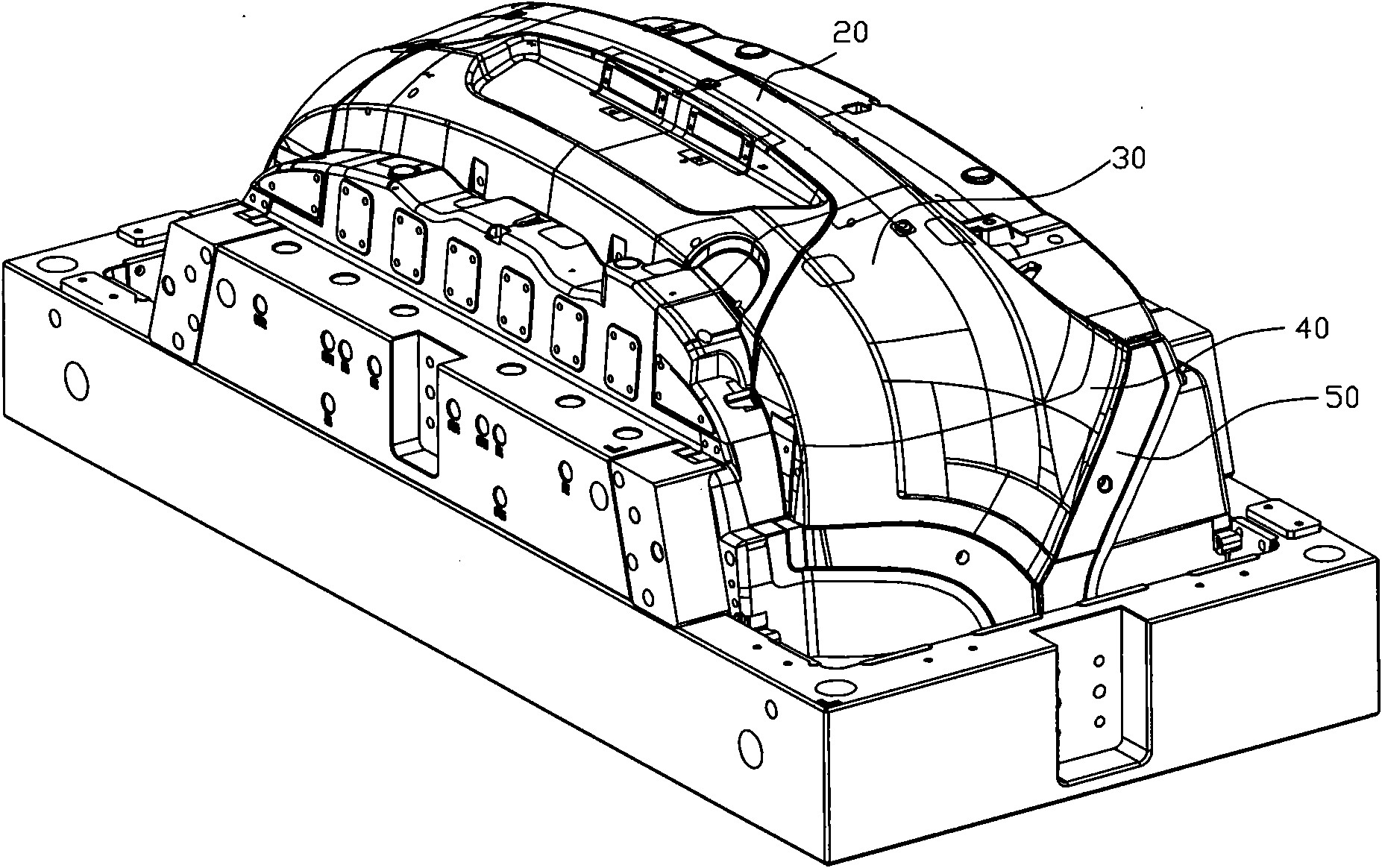
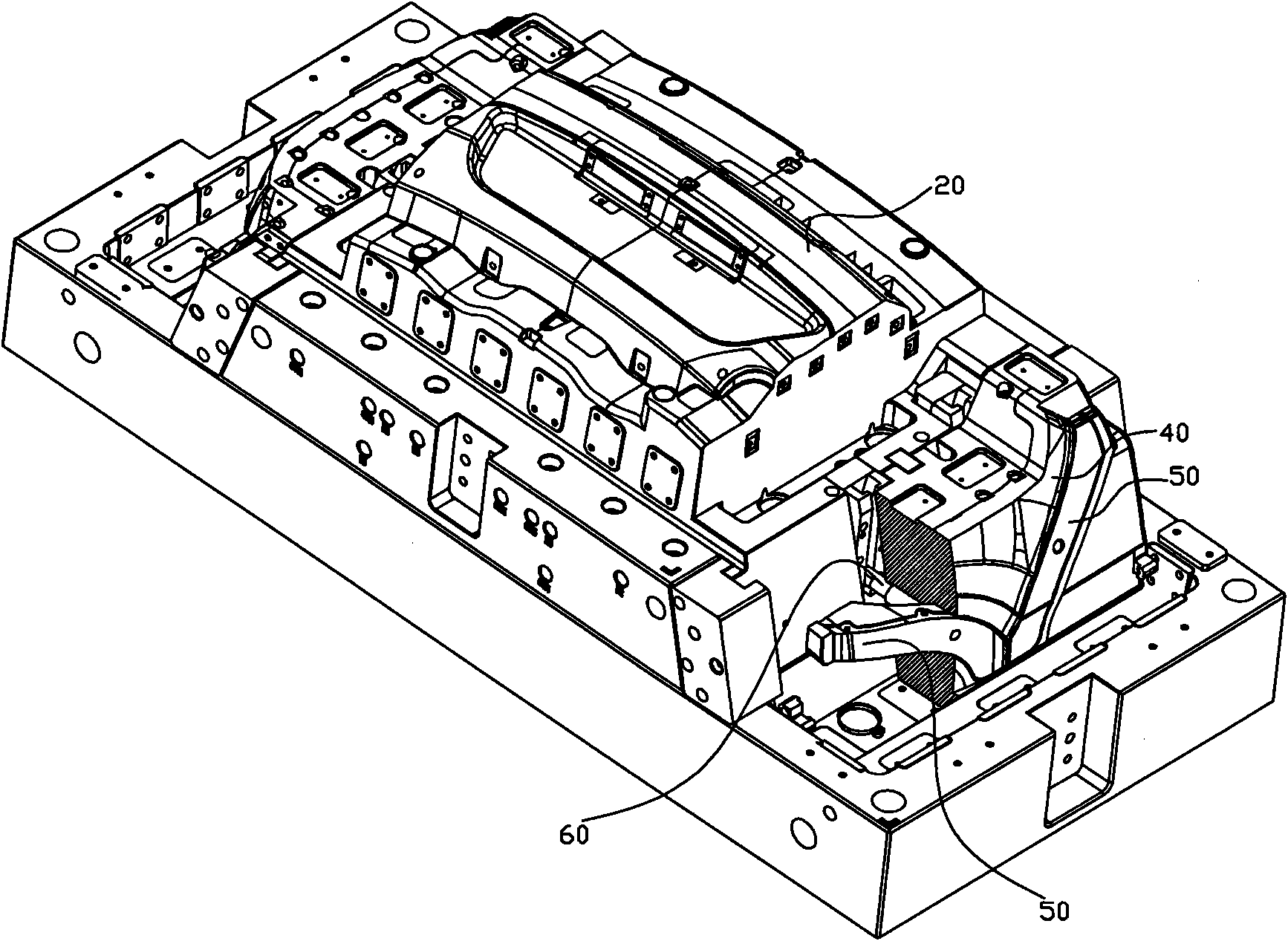
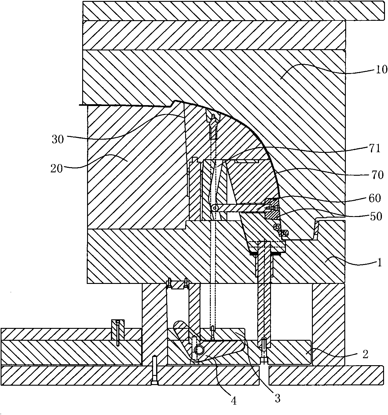
[0016] Such as image 3 , 4 As shown, the mold includes a front mold 10 and a rear mold assembly, the front mold 10 is integrated, and the edge of its molding surface extends to the side of the decorative surface of the product to be processed; the rear mold assembly includes a centrally arranged rear mold core 20 , the rear mold straight top core 30 is arranged on the side of the rear mold core 20, and the inclined top core 40 is arranged along the side of the rear mold straight top core 30, and the flanging forming block 50 is arranged on the inclined top core 40, and the flanging is formed. Block 50 cooperates with the flanging forming groove 41 provided on the inclined top core 40 to form a product flanging forming cavity, and the edge joint of flanging forming block 50, flanging forming groove 41 and front mold 10 constitutes a product parting position. The position is located on the side of the decorative surface of the product. The so-called side refers to the side tha...


PUM


Abstract

The invention aims to provide a mould, which is convenient for demoulding and ensures a product parting line located at the side of a veneer to improve the smoothness and flatness of the veneer. The mould comprises an integrative front mould component and a rear mould component, the edge of the moulding surface of the front mould component extends to the side of the veneer of the product to be processed, the rear mould component comprises a rear mould mold core, a rear mould straight-acting mold core, a tilt-acting mold core, a flanging moulding block and the like; the rear mould mold core, the straight-acting mold core and the tilt-acting mold core of the rear mould are combined and the flanging moulding block is matched with the flanging moulding slot arranged on the tilt-acting mold core mutually to conveniently realize the demoulding process, and the outer surface of the produced product is smooth and trim, namely the veneer, thereby avoiding the phenomena of flashing and burr on the outer surface of the product, having no need of implementing finishing and polishing treatment on the outer surface and significantly improving production efficiency.

Description

technical field [0001] The present invention relates to injection molding molds. Background technique [0002] In the process of traditional mold processing, due to the consideration of demoulding, the mold often adopts an external parting structure. For example, the structure design of the traditional bumper mold for automobiles is external splitting, and the two inclined roof structures are formed. The products produced will inevitably produce flashes and burrs on the decorative surface of the products. A large amount of pre-treatment work is required for the formed product before painting, that is, repairing flashes, grinding and other processes, which is time-consuming and laborious, and brings unnecessary troubles to subsequent work, such as Figure 11 As shown, the edge of the product 80 is the parting line 81, and the flash and burrs produced after injection molding are kept at the parting line 81, and they are within the normal visual range, that is to say, if this ...

Claims


Application Information

Patent Timeline
IPC IPC(8): B29C45/26B29L31/30
Inventor 曹树文丁保国
Owner 合肥星通橡塑有限公司
Learn More