
Indoor machine of air conditioner

A technology of air conditioner indoor unit and fan, which is applied in the direction of air conditioning system, space heating and ventilation, space heating and ventilation details, etc., and can solve the problems of air duct influence and inability to install

Inactive Publication Date: 2010-09-08
GUANGDONG MIDEA ELECTRIC APPLIANCES CO LTD
View PDF5 Cites 13 Cited by
  • Summary
  • Abstract
  • Description
  • Claims
  • Application Information

AI Technical Summary

Problems solved by technology

However, the existing wall-mounted air conditioner indoor unit is affected by the air duct, and the above position obviously cannot be installed.

Method used


Image

  • Indoor machine of air conditioner
  • Indoor machine of air conditioner
  • Indoor machine of air conditioner

Examples


Embodiment 1

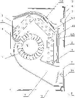
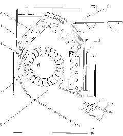
[0022] like figure 1 , 2 As shown, the air conditioner indoor unit of the present invention includes a housing 1, a front panel 2, a heat exchanger 3, a water tray 4, a fan 5, an air inlet 6, an air outlet 7 and an air duct 8, wherein the front panel 2 is installed on The front part of the casing 1, the heat exchanger 3, the water receiving tray 4 and the fan 5 are installed in the cavity formed by the casing 1 and the front panel 2, and the air duct 8 is arranged in the cavity formed by the casing 1 and the front panel 2, The blower fan 5 is installed in the air duct 8 , the air outlet 7 is arranged on the housing 1 or the front panel 2 , the air outlet 7 is provided with an air supply deflector 9 , and the air inlet 6 is arranged on the top of the front panel 2 . In order to increase the airflow distribution and prevent dust, a return air deflector 10 is provided at the air inlet 6, and the return air deflector 10 can have only one piece or multiple pieces, and between the ...

Embodiment 2

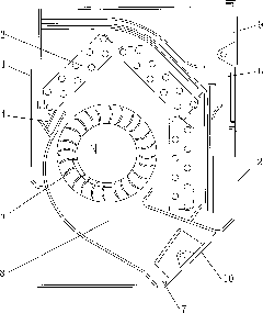
[0024] like image 3 As shown, the difference between this embodiment and Embodiment 1 is that the air outlet 7 is arranged on the housing 1 below the front panel 2 . Other structures are the same as in Embodiment 1.

Embodiment 3

[0026] The difference between this embodiment and Embodiment 1 lies in that: the air outlet 7 is arranged on the bottom 11 of the casing, and the bottom 11 of the casing is a flat plate structure. For better air outlet, the bottom 11 of the casing has an arc portion extending forward and upward, and the air outlet 7 is arranged on the arc portion.


PUM


Abstract

The invention relates to an indoor machine of an air conditioner, which comprises a casing, a front panel, a heat exchanger, a defrosting tray, a fan, an air inlet, an air outlet and an air passage, wherein the front panel is installed at the front part of the casing, the heat exchanger, the defrosting tray and the fan are installed in a cavity body formed by the casing and the front panel, the air passage is arranged in the cavity body formed by the casing and the front panel, the fan is installed in the air passage, the air outlet is arranged on the casing or the front panel, and the position of the air outlet is provided with an air-supply air deflector. The indoor machine of the air conditioner is characterized in that the air inlet is arranged at the upper part of the front panel. On the basis of the structure of the indoor machine of a traditional wall-hanging type air conditioner, the invention moves the air inlet from the top of the casing to the upper part of the front panel. By the structural design, air does not need to enter the indoor machine of the air conditioner from the top any more, so that the indoor machine of the air conditioner can be hung and installed on a ceiling or embedded in a wall or furniture and can adapt to more installation spaces and positions.

Description

technical field [0001] The invention belongs to the technical field of air conditioners, and in particular relates to an indoor unit of an air conditioner. Background technique [0002] At present, the split wall-mounted indoor unit includes a shell, a front panel, a heat exchanger, a water tray, a fan, an air inlet, an air outlet, and an air duct. The water tray and the fan are installed in the cavity formed by the shell and the front panel, the air duct is set in the cavity formed by the shell and the front panel, the fan is installed in the air duct, and the air outlet is set on the shell or the front panel. An air supply deflector is installed, the air inlet is arranged on the top plate of the casing, and a grille and an air filter are arranged at the air inlet. The indoor unit of the air conditioner with this structure can usually only be installed in the middle and upper part of the room, and cannot be close to the ceiling, otherwise it will affect the air intake of t...

Claims


Application Information

Patent Timeline
Patent Type & Authority Applications(China)
IPC IPC(8): F24F1/00F24F13/28F24F13/20
Inventor 邓明义曾祥兵
Owner GUANGDONG MIDEA ELECTRIC APPLIANCES CO LTD
Learn More