
Tailing removal method of cold shear machine

A cold shearing machine and tail sweeping technology, which is applied in the field of steel processing to prevent the overturn from being blocked, support the overturning smoothly, and facilitate the hinged installation.

Active Publication Date: 2020-07-17
MAANSHAN CITY ZHICHENG MACHINE & ELECTRIC
View PDF12 Cites 0 Cited by
  • Summary
  • Abstract
  • Description
  • Claims
  • Application Information

AI Technical Summary

Problems solved by technology

[0008] Aiming at the problem in the prior art that there is no good method for cleaning the tailings of the cold shearing production line with a compact layout space, the present invention provides a method for cleaning the tails of cold shears, using a new type of tailing device for cold shears, which can control The platen is turned over with a specific trajectory in a limited space to realize the removal of steel tailings in a production line with a compact layout, which has high application value

Method used


Image

  • Tailing removal method of cold shear machine
  • Tailing removal method of cold shear machine
  • Tailing removal method of cold shear machine

Examples


Embodiment 1

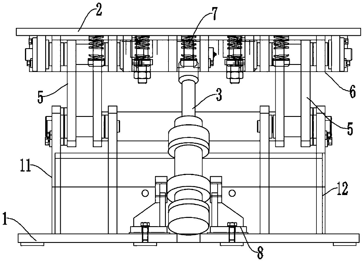
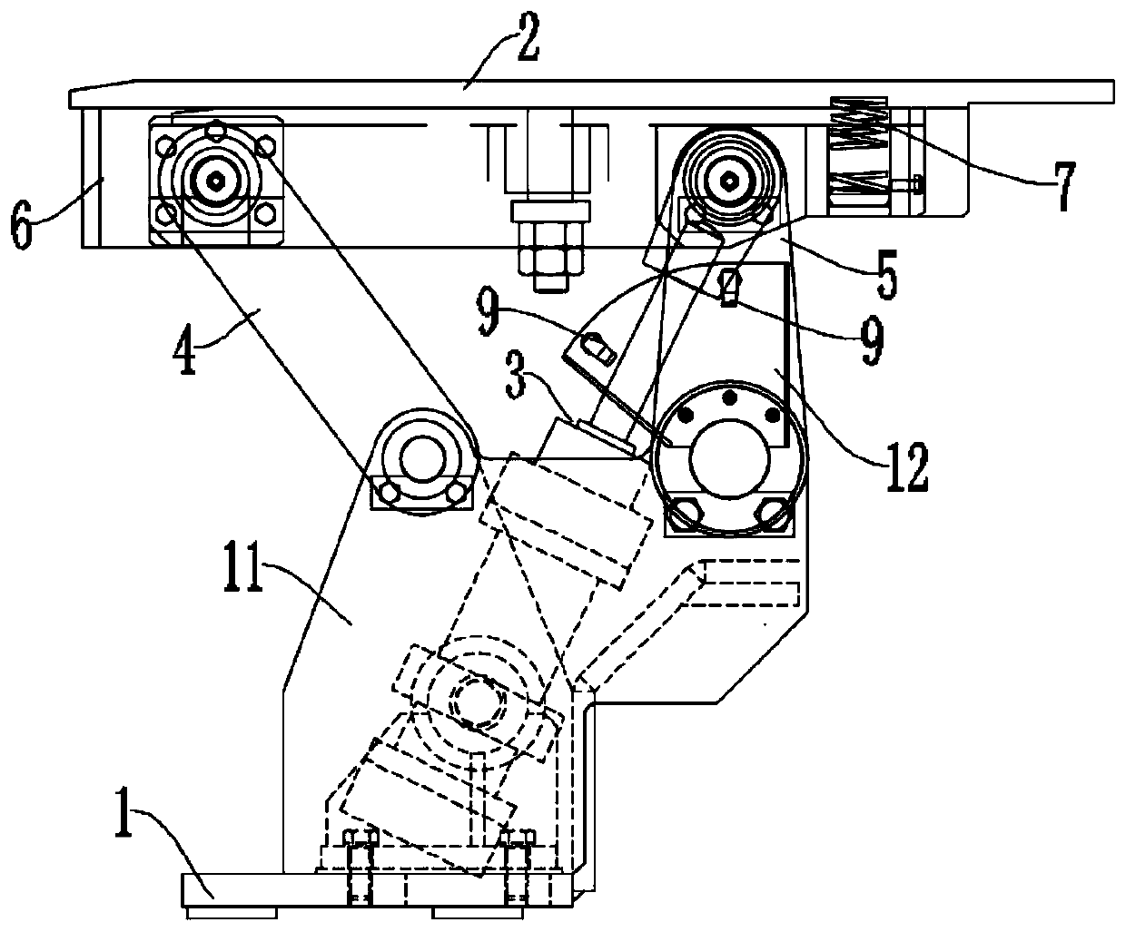
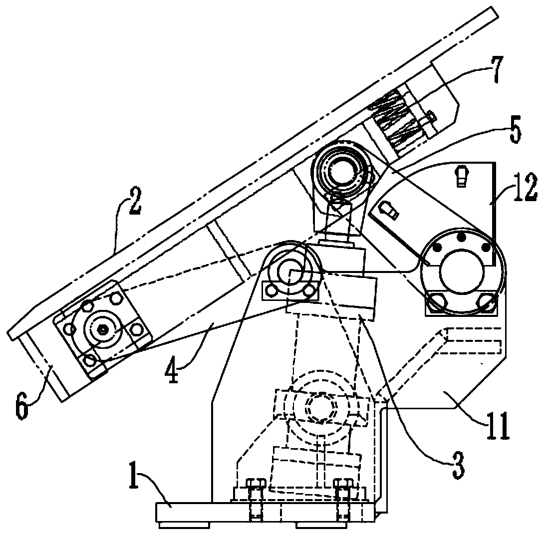
[0039] A new type of tailing device for cold shears is used in the cold shearing production line of steel. It is arranged before the upper and lower cutting edges of the cold shears. After the steel is cut, the remaining steel tails on the platen are removed by turning the platen. The specific structure and working principle are described in detail below.

[0040] Such as Figure 1 to Figure 3 As shown, the tailing device of the cold shear mainly includes a base 1 as an installation base, a platen 2 for receiving steel, a drive cylinder 3 for turning over the console plate 2, a front rocker 4 and a rear rocker 5 . Wherein, one end of the driving cylinder 3 , the front rocker 4 and the rear rocker 5 are all hingedly connected to the platen 2 , and the other end is hingedly connected to the base 1 .

[0041] Specifically, in order to provide more convenient installation space for the drive cylinder 3, the front rocker 4 and the rear rocker 5, a pair of supports 11 are symmetric...

Embodiment 2

[0049] Such as Figure 4 As shown, it is a cold shearing production line with a relatively compact layout space. When the cold shearing machine shears steel, the platen is close to the side wall of the lower shearing edge a, and the upper shearing edge b and the steel pressing mechanism c are cold. The other parts of the shearing machine are all located above the lower cutting edge a and the platen, and there are devices such as guide rollers at the other end of the platen, which are not shown in the figure. In this case, it is difficult to arrange independent process equipment on the side and above the platen, and remove the tailings by pushing the material above the roller table of the platen. Even if independent process equipment can be arranged, due to Removal is done by pushing the tail off the rear end, so it is difficult to divide the longer tail.

[0050] Therefore, the inventor considers that an oil cylinder is arranged below the platen, and the console plate is flip...


PUM


Abstract

The invention discloses a tailing removal method of a cold shear machine, and belongs to the field of steel machining. A novel tailing removal device of the cold shear machine is adopted. According tothe operation process, in the initial state, a telescopic rod of a drive cylinder is controlled to be in a stretching state, and a platen is in a horizontal state; and after steel shearing finishes,the drive cylinder contracts, front rocking bars and rear rocking bars are driven to rotate along the hinged points of the front rocking bars and rear rocking bars and a base, the front rocking bars and the rear rocking bars drive the platen to turn over along the set track, after the rear rocking bars arrive at the set position, the drive cylinder stops contraction, and removal of tailings on theplaten is completed. According to the tailing removal method, the platen can be controlled to turn over in limited space according to the specific track, steel tailings are moved in a production linecompact in layout space, and high application value is achieved.

Description

technical field [0001] The invention belongs to the technical field of steel processing, and more specifically, relates to a tailing method of a cold shear. Background technique [0002] The cold shear is a kind of equipment used to cut the steel to a fixed length. The working process is usually to convey the steel in the roller table and pass through the upper and lower cutting edges of the cold shearing machine continuously. After the steel protrudes out of the lower cutting edge for a certain distance , firstly control the pressing steel mechanism above the workbench to press the steel tightly, and then make the upper shearing edge descend and cooperate with the lower shearing edge to cut the steel. During the cold shearing process, the residual steel tailings on the workbench and roller table after cutting to length will affect the continuity of the process, so they need to be removed. The traditional cold shearing machine has insufficient automation in the removal of s...

Claims


Application Information

Patent Timeline
Patent Type & Authority Applications(China)
IPC IPC(8): B23D33/00
CPCB23D33/00
Inventor 杨建华许同海方朝辉
Owner MAANSHAN CITY ZHICHENG MACHINE & ELECTRIC
Learn More