
MAV

A micro air vehicle and flying wing technology, applied in the field of micro air vehicles, can solve the problems of reduced aircraft payload, poor aircraft roll stability, small body capacity, etc., so as to improve wind resistance and flight stability, improve system Reliability, the effect of reducing gust overload

Inactive Publication Date: 2012-02-08
TSINGHUA UNIV
View PDF2 Cites 0 Cited by
  • Summary
  • Abstract
  • Description
  • Claims
  • Application Information

AI Technical Summary

Problems solved by technology

[0003] 1. Due to the small size and low flight speed, the flight Reynolds number is low; the low Reynolds number causes laminar boundary layer separation and laminar turbulence transition on the wing surface, which reduces the lift-to-drag ratio and increases the drag coefficient
[0004] 2. Due to the low aspect ratio, strong wing surface vortex is induced, which makes the aircraft force complicated; the low aspect ratio itself makes the aircraft roll stability worse, and the existence of wingtip vortex further deteriorates the roll stability
[0005] 3. Due to the small weight, low inertia and low flight speed, the aircraft is vulnerable to disturbance and has poor wind resistance
[0008] 1. The small capacity of the fuselage makes it difficult to arrange the flight control system and task load, which in turn affects the system performance;
[0009] 2. The split design and layout of the airborne circuit not only occupies the limited fuselage capacity, but also reduces the payload of the aircraft

Method used


Image

  • MAV
  • MAV
  • MAV

Examples


Embodiment Construction

[0030] The present invention will be further described in detail below in conjunction with the accompanying drawings and specific embodiments.

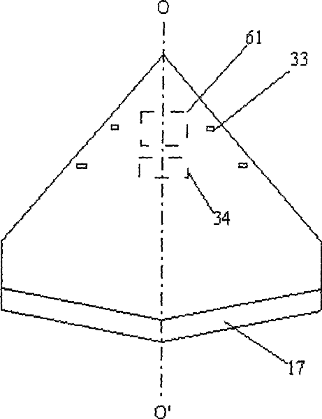
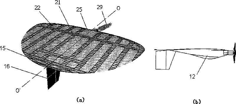
[0031] figure 2 An embodiment of the micro air vehicle according to the present invention is shown, and the structure of the micro air vehicle of this embodiment is as described in the document "Wu Huaiyu, Micro air vehicle: configuration, analysis, fabrication and test, IEEE / ASME TRANSACTIONS ONMECHATRONICS, VOL.9, NO. 1, recorded in MARCH2004". The aircraft adopts a flying wing aerodynamic layout, and the aircraft is composed of a skeleton and a skin. The only difference is that if figure 2 As shown, the skin is a flexible circuit board, on which a flow velocity sensor array 33 , a sensor signal conditioning circuit 34 , and a sensor data acquisition and recording circuit 61 are integrated. The sensor array 33 is arranged on the upper and lower surfaces of the leading edge of the wing, and the sensor signal conditioning circuit...


PUM


Abstract

The invention provides a micro-aircraft, comprising a fuselage and a wing fixed on the fuselage, the wing includes a wing frame and a skin bonded to the wing frame, wherein at least part of the skin is integrated with Flexible circuit boards for onboard circuitry. Here, the wing skin integrates on-board circuits and devices, so that the wings simultaneously become the carrier of wing surface flow field sensors and other related on-board circuits and devices, which reduces the weight of the aircraft and provides more space for other mission loads. More installation space. The wing skin of the invention integrates on-board circuits and devices, which facilitates the electrical connection of various parts of the aircraft, improves system reliability, and also facilitates the electrical expansion of the aircraft.

Description

technical field [0001] The present invention relates to a micro-aircraft, in particular to a micro-aircraft integrating on-board circuits and devices. Background technique [0002] Since the United States proposed the concept of "micro-aircraft" in 1992, micro-aircraft have attracted much attention because of their special purposes. Some countries have invested special funds to develop aircraft with a wingspan of less than 1 meter or even less than 150 mm, and have achieved considerable results. The tasks performed by micro air vehicles mainly include: aerial reconnaissance, target indication, communication relay, etc. The stability and controllability of the aircraft itself are the prerequisites for performing various tasks. The small size makes the MAV have advantages such as low hovering speed, but from the perspectives of aerodynamics, control performance, maneuverability, etc. Consider, MAVs have some disadvantageous main features as follows: [0003] 1. Due to the s...

Claims


Application Information

Patent Timeline
Patent Type & Authority Patents(China)
IPC IPC(8): H05K1/02A63H27/18B64C39/00
Inventor 朱荣周兆英费海平王劲东张福星
Owner TSINGHUA UNIV
Learn More