Supercharge Your Innovation With Domain-Expert AI Agents!

Mechanical rotary switch

A rotary switch, mechanical technology, applied in the direction of electric switches, electrical components, circuits, etc.

Active Publication Date: 2010-09-08
SCHNEIDER ELECTRIC IND SAS
View PDF4 Cites 4 Cited by
  • Summary
  • Abstract
  • Description
  • Claims
  • Application Information

AI Technical Summary

Problems solved by technology

[0004]In the above mechanical rotary switch, when the knob is rotated to different positions, different switch functions can be realized, but when the knob is rotated from different directions (clockwise and counterclockwise) direction) to the same position, but can only achieve the same function, that is, the rotation position of the rotation axis and the function are directly corresponding

Method used


Image

  • Mechanical rotary switch
  • Mechanical rotary switch
  • Mechanical rotary switch

Examples


Embodiment Construction

[0017] Hereinafter, the present invention will be described in more detail according to preferred embodiments. In all figures, the same elements are denoted by the same reference numerals. The drawings and associated descriptions are illustrative only and not restrictive.

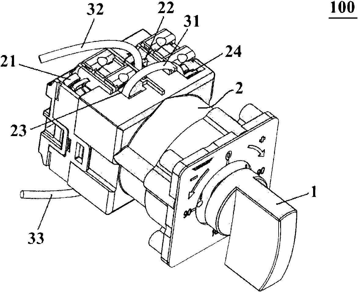
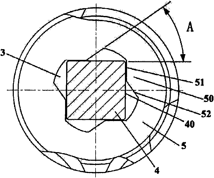
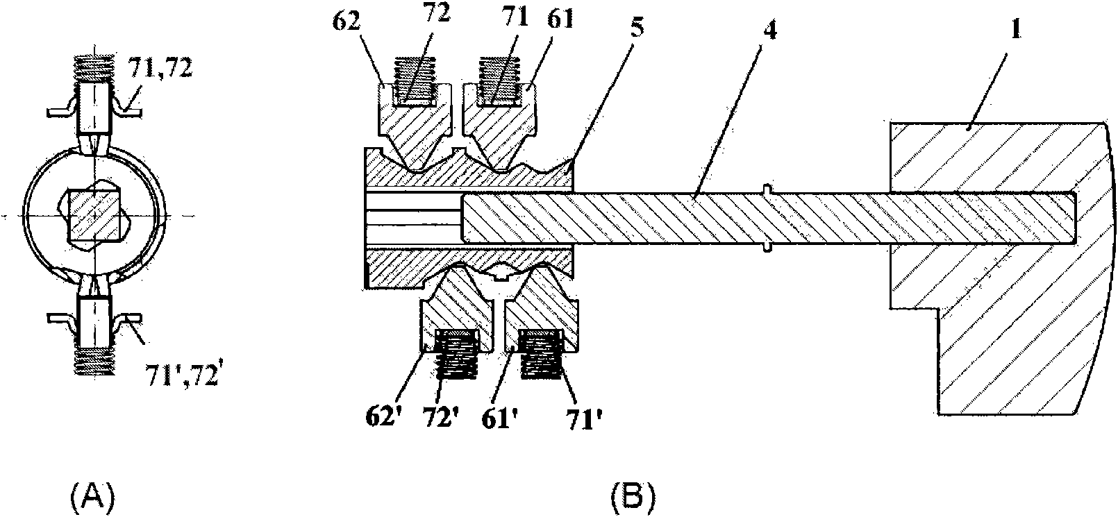
[0018] The mechanical rotary switch according to the present invention can be in the form of a cam switch, etc., and includes a switch body with a shaft hole and a rotating shaft rotatably inserted in the shaft hole. Working status (function). Compared with the traditional mechanical rotary switch, the mechanical rotary switch according to the present invention provides a new mechanical rotary switch by configuring the matching relationship between the shaft hole and the rotary shaft, which can realize the rotation position of the rotary shaft and the switch The corresponding functions are separated, for example, so that the rotating shaft can realize different functions when rotating clockwise and counte...


PUM


Abstract

The embodiment of the invention provides a mechanical rotary switch comprising a switch body provided with a shaft hole, and a rotating shaft which is inserted in the shaft hole rotatably and used for changing the working state of the mechanical rotary switch, wherein the shaft hole is internally provided with a first pair of supporting faces forming a first included angle and projecting towards the interior of the shaft hole and a first pushing face corresponding to the first pair of supporting faces is formed on the rotating shaft; when the rotating shaft rotates to a first direction, one of the first pair of supporting faces is pushed by the first pushing face corresponding to the rotating shaft; when the rotating shaft rotates to a second direction opposite to the first direction, the other one of the first pair of supporting faces is pushed by the first pushing face corresponding to the rotating shaft; and when one of the first pair of supporting faces abuts against the first pushing face corresponding to the rotating shaft, the other one of the first pair of supporting faces and the first pushing face corresponding to the rotating shaft form a second included angle.

Description

technical field [0001] The invention relates to a mechanical rotary switch. Background technique [0002] The traditional mechanical rotary switch can realize different functions when the knob is rotated to any angle within the range of 360°. figure 1 A schematic diagram of such a conventional mechanical rotary switch is shown. [0003] like figure 1 As shown, the mechanical rotary switch 100 includes a rotating shaft (not shown) connected to the knob 1 and a switch body 2, and the rotating shaft is inserted into a shaft hole (not shown) in the switch body 2 . Connecting terminals 21, 22, 23 and 24 are arranged on the mechanical switch 100, and connecting terminals 21', 22', 23' and 24' are also arranged symmetrically. The wires 31, 32 and 33 are respectively connected to the connection terminals to form a circuit. When the knob 1 is rotated to a gear position, the terminals 21, 22, 23 and 24 and 21', 22', 23' and 24' are in the on or off state of the functional requirem...

Claims


Application Information

Patent Timeline
IPC IPC(8): H01H19/20H01H19/42
Inventor 曾晓菁张锋禇毅成张涛
Owner SCHNEIDER ELECTRIC IND SAS
Features
  • R&D
  • Intellectual Property
  • Life Sciences
  • Materials
  • Tech Scout
  • Unparalleled Data Quality
  • Higher Quality Content
  • 60% Fewer Hallucinations
Learn More