
Water sensing devices and methods utilizing same to control flow of subsurface fluids

A technology for controlling fluids and fluids, which can be used in the fields of production of fluids, valve devices of wellbore/well, earth-moving drilling, etc., which can solve the problems of reducing the quantity and quality of oil produced

Inactive Publication Date: 2010-09-08
BAKER HUGHES INC
View PDF5 Cites 5 Cited by
  • Summary
  • Abstract
  • Description
  • Claims
  • Application Information

AI Technical Summary

Problems solved by technology

Likewise, water coning can cause water to flow into the oil production stream, which can also reduce the quantity and quality of recovered oil

Method used


Image

  • Water sensing devices and methods utilizing same to control flow of subsurface fluids
  • Water sensing devices and methods utilizing same to control flow of subsurface fluids
  • Water sensing devices and methods utilizing same to control flow of subsurface fluids

Examples


Embodiment Construction

[0017] The present invention relates to apparatus and methods for controlling the production of hydrocarbon production wells. The present invention allows various forms of embodiment. What has been shown in the drawings and described in detail herein is a specific embodiment of the invention. It is to be understood that the invention is to be considered as an example of the principles of the invention and not to limit the invention to what has been shown and described herein. Further, although an embodiment has been described as having one or more features or a combination of two or more features, such feature or feature combination should not be considered essential unless expressly stated otherwise.

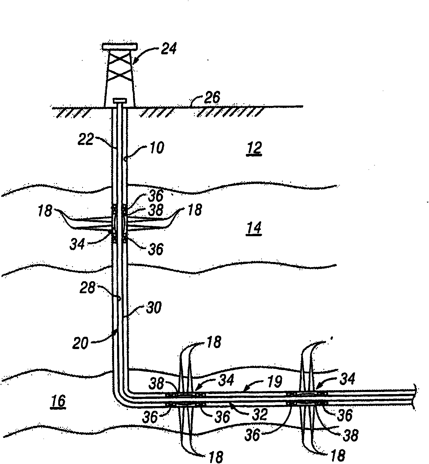
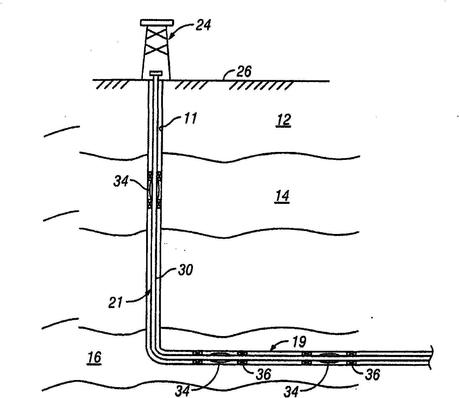
[0018] see first figure 1 , shows an exemplary wellbore 10 drilled through a formation 12 into a pair of formations 14, 16 from which hydrocarbons are expected to be produced. A metal casing is inserted in the wellbore 10, as is well known in the art, and a number of perforat...


PUM


Abstract

An apparatus for controlling fluid flow in a wellbore includes a reactive element that reacts when exposed to a fluid and a flow control device configured to control a flow of the fluid. The flow control device may be actuated by a reaction of the reactive element to the fluid. In embodiments, the reactive element reacts by exhibiting a change in a material property. The reaction of the reactive element may be reversible. In embodiments, the reactive element may be a shape memory polymer. The flow control device may include an actuating element operably coupled to the reactive element. The reaction of the reactive element to a given fluid releases the actuating element to actuate the flow control device.

Description

technical field [0001] The present invention generally relates to systems and methods for selectively controlling fluid flow into a wellbore. Background technique [0002] Hydrocarbons, such as oil and gas, are produced from subterranean formations using wellbores drilled into the formation. Such wells are typically completed by placing a casing along the length of the wellbore and drilling the casing adjacent each such production zone to extract formation fluids (eg, hydrocarbons) into the wellbore. These mining areas are sometimes separated from each other by installing a spacer between the mining areas. Fluids entering the wellbore from each production zone are drawn into tubulars that extend to the surface. It is desirable to have substantially uniform discharge along the production zone. Uneven discharge can lead to undesirable conditions such as aggressive air or water cones. In the case of production wells, for example, gas cones can cause gas to flow into the wel...

Claims


Application Information

Patent Timeline
Patent Type & Authority Applications(China)
IPC IPC(8): E21B43/00E21B34/06
CPCE21B43/32E21B43/12E21B2200/02
Inventor S·L·克罗S·R·海特K·C·霍姆斯P·兰詹
Owner BAKER HUGHES INC
Learn More