Protector of cylinder lock

A technology of protection device and cylinder lock, which is applied to the device for preventing theft of bicycles, construction lock, transportation and packaging, etc., to achieve the effect of shortening the length and improving operability

Active Publication Date: 2010-09-15
HONDA LOCK MFG CO LTD
View PDF6 Cites 8 Cited by
  • Summary
  • Abstract
  • Description
  • Claims
  • Application Information

AI Technical Summary

Problems solved by technology

[0004] However, in the device disclosed in the aforementioned Patent Document 1, since the member that holds the shutter at the open position is configured to move alon

Method used


Image

  • Protector of cylinder lock
  • Protector of cylinder lock
  • Protector of cylinder lock

Examples


no. 1 example

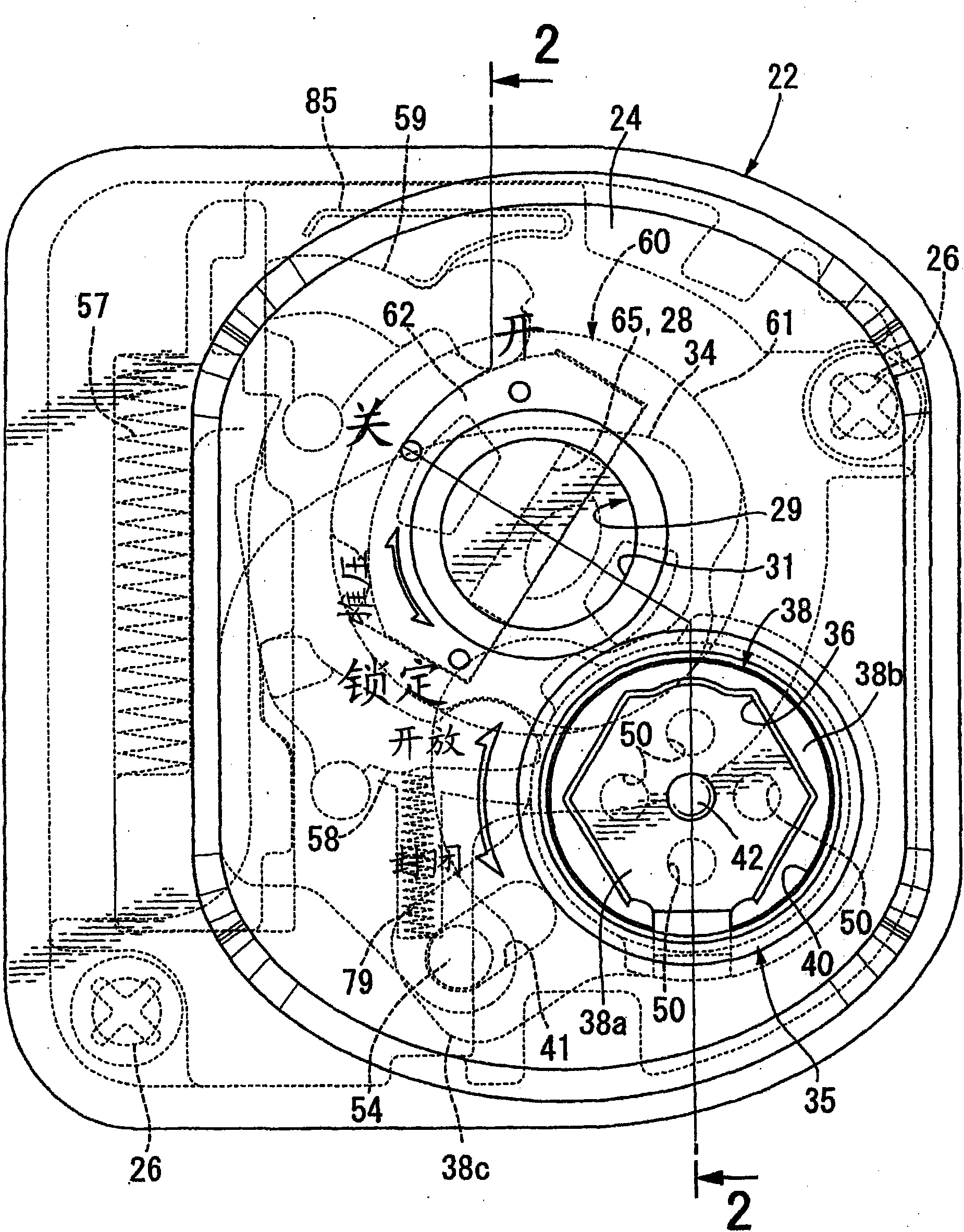
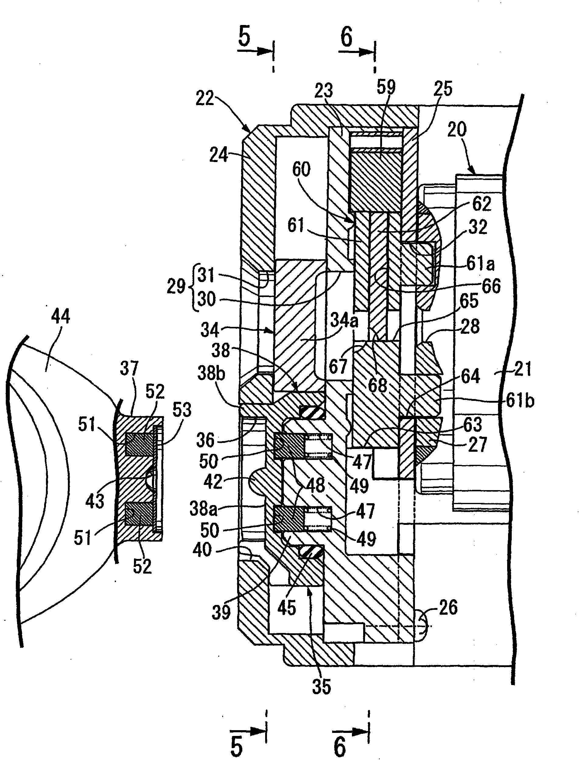
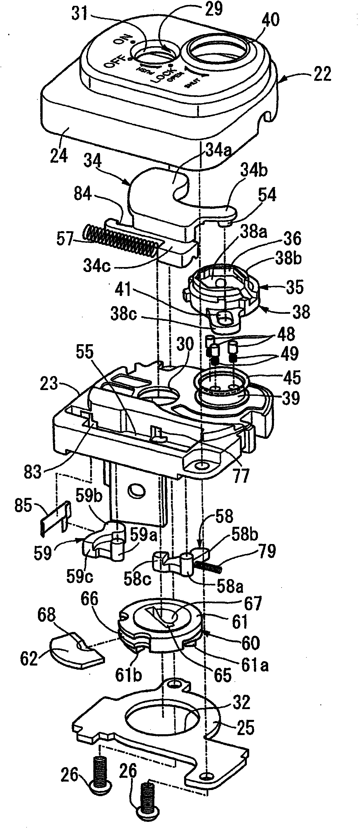
[0062] Figure 1 to Figure 15 It is a figure which shows the 1st Example of this invention.

[0063] First, in figure 1 and figure 2 Among them, a cylinder 21 of a cylinder lock 20 for a vehicle (for example, a motorcycle) is provided on a steering riser (not shown) of a vehicle body frame, and the front end of the cylinder 21 is covered by a housing 22 . The casing 22 includes: a shell member 23 made of a non-magnetic material, which is installed on the front end of the cylinder 21; a cover member 24 made of a non-magnetic material, which is installed on the shell member 23; and a flat back plate 25 , the back plate 25 clamps the shell part 23 between it and the cover part 24, by tightening the shell part 23, the cover part 24 and the back plate 25 using a plurality of (for example two) threaded parts 26, 26 The casing 22 is formed by solidifying, and the casing 22 is fixed to the cylinder 21 .

[0064]The cylinder lock 20 has an inner cylinder 27 inserted into the cylin...

no. 2 example

[0108] Figure 16 ~ Figure 25 It is a figure which shows the 2nd Example of this invention.

[0109] In addition, parts corresponding to those of the first embodiment are denoted by the same reference numerals and are only shown in the drawings, and detailed descriptions are omitted.

[0110] First, in Figure 16 and Figure 17 In the cylinder lock 20 for a vehicle (for example, a motorcycle), the front end portion of the cylinder 21 is covered by the housing 90 . The casing 90 includes: a shell member 91 made of a non-magnetic material, which is installed on the front end of the cylinder 21; a cover member 92 made of a non-magnetic material, which is installed on the shell member 91; and a flat back plate 93 , the back plate 93 clamps the shell part 91 between it and the cover part 92, by tightening the shell part 91, the cover part 92 and the back plate 93 using a plurality of (for example two) threaded parts 94, 94 The casing 90 is formed by solidifying, and the casing ...

no. 3 example

[0155] Figure 26 ~ Figure 40 It is a figure which shows the 3rd Example of this invention.

[0156] In addition, parts corresponding to those of the above-mentioned first and second embodiments are denoted by the same reference numerals and are only shown in the figures, and detailed explanations are omitted.

[0157] First, in Figure 26 and Figure 27 Among them, a cylinder 21 of a cylinder lock 20 for a vehicle (for example, a motorcycle) is provided on a steering riser (not shown) of a vehicle body frame, and the front end of the cylinder 21 is covered by a housing 132 . The casing 132 includes: a shell member 133 made of a non-magnetic material, which is installed on the front end of the cylinder 21; a cover member 134 made of a non-magnetic material, which is installed on the shell member 133; and a flat back plate 135 , the back plate 135 clamps the shell part 133 between it and the cover part 134, by tightening the shell part 133, the cover part 134 and the back pl...


PUM


Abstract

In the protector of a cylinder lock arranged such that a shutter plate is reset automatically from open position to closed position as a mechanical key is withdrawn from a key hole, a spring means (57), first and second engaging members (58, 59), and a cam means (60) for operating the engaging members are housed in a casing (22) to operate along a plane intersecting the axis of a key hole (28) perpendicularly. The cam means makes the first engaging member (58) engage with the shutter plate (34) in response to operation of the shutter plate to the open position, makes the second engaging member (59) engage with the shutter plate in response to insertion of the mechanical key (33), disengages the first engaging member from the shutter plate in response to rotary operation to the on position, and disengages the second engaging member from the shutter plate in response to withdrawal of the mechanical key. Since the mechanical key is not required to be formed long, the protector of a cylinder lock can be constituted compactly.

Description

technical field [0001] The invention relates to a protection device for a cylinder lock. The protection device for a cylinder lock comprises: a housing which has an insertion hole and is fixed to a cylinder body of the cylinder lock. The insertion hole corresponds to a keyhole, and the keyhole is arranged on an inner cylinder that the cylinder lock has; a gate that can move along a plane perpendicular to the axis of the keyhole between a closed position that closes the insertion hole and an open position that opens the insertion hole, And the gate is accommodated in the housing; and a magnetic lock capable of holding the gate in the closed position when locked, and locking the gate from the closed position to the closed position when unlocked. Operated in an open position, the gate is automatically reset from the open position to the closed position as the mechanical key is withdrawn from the keyhole. Background technique [0002] For example, in Patent Document 1, there is...

Claims


Application Information

Patent Timeline
IPC IPC(8): E05B17/18B62H5/06E05B65/12
CPCE05B17/142E05B47/0038B62H5/06E05B17/18
Inventor 黑岩丈展安藤孝文井上史朗撒姆恩格·尼瓦特
Owner HONDA LOCK MFG CO LTD
Why Eureka
Try Eureka