Luminous switch structure and push button

A switch and button technology, which is applied in the field of illuminated switch structures, can solve the problems of insufficient records and the button cannot be moved smoothly, and achieves the effects of excellent operation reliability and excellent durability.

Active Publication Date: 2015-04-08
YAMAHA CORP
View PDF7 Cites 0 Cited by
  • Summary
  • Abstract
  • Description
  • Claims
  • Application Information

AI Technical Summary

Problems solved by technology

On the other hand, if the diameters of the guide pin and the guide hole are too close, the button will not move smoothly if the direction of the pressing operation is different from the direction of movement of the guide pin.
From this point of view, in the structure described in this patent document, although it is described that a cylindrical guide member for allowing the pin to slide well is inserted on the base plate, the deviation between the operating direction and the moving direction of the pin is difficult. How to reliably achieve smooth motion is not well documented

Method used


Image

  • Luminous switch structure and push button
  • Luminous switch structure and push button
  • Luminous switch structure and push button

Examples


Embodiment Construction

[0026] Hereinafter, embodiments of the present invention will be described with reference to the drawings. The same or similar parts in the drawings are assigned the same reference numerals, and descriptions of parts are omitted.

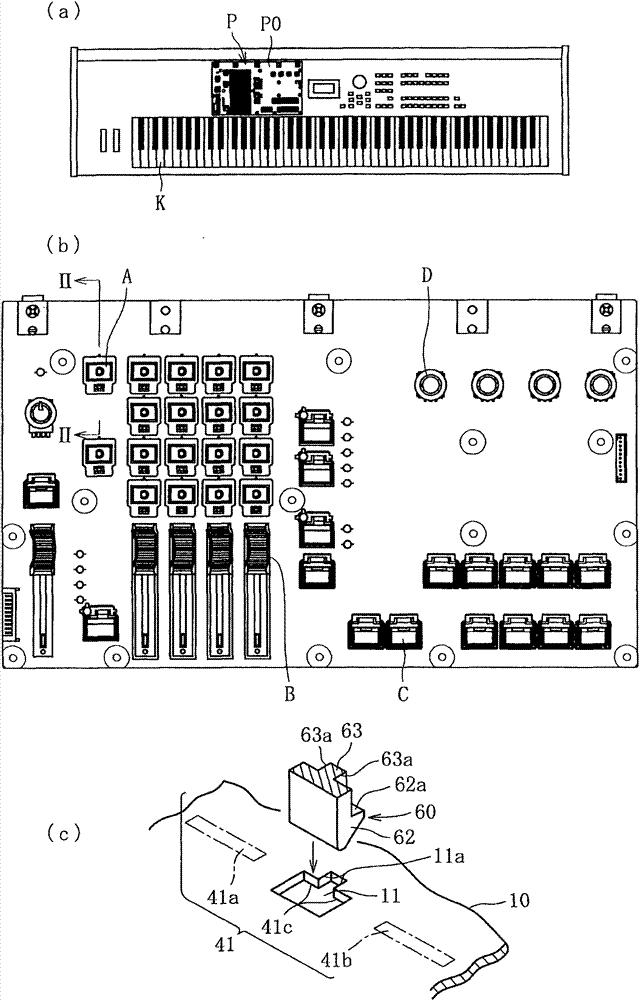
[0027] figure 1 (a) is a plan view showing an electronic piano equipped with the illuminated switch structure of the present invention. The electronic piano has a control panel part P on the inner side of the keyboard K (the side away from the player), and the control panel part P is used to set or switch control parameters such as timbre, sound quality, and sound effects. figure 1 (b) is an enlarged representation of the control panel part P. FIG. On the control panel part P, there are button A with illuminated switch structure, sliding operation piece B, button C without light function, rotary operation piece D, and the like.

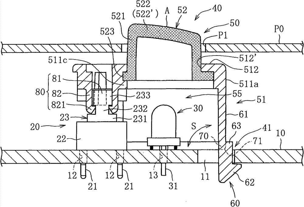
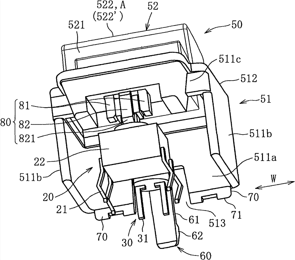
[0028] figure 2 and image 3 It is a light-emitting switch structure showing one embodiment of the present inventi...


PUM


Abstract

The present invention provides a luminous switch structure with high durability and excellent reliability, and a push button. The luminous switch structure comprises the following components: a substrate (10) which is provided with an insertion hole (11); a switch unit (20) which is fixed on the substrate (10) and is provided with a driven part (23) that is set to reciprocate for the action of switch; an illumination part (LED30); and a push button (40). The push button (40) comprises the following components: a light penetration part (522) which is provided at the outer end and forms a space for accommodating the illumination part and causes the light of the illumination part to pass through; a fixing paw (60) which extends from one side part (511a) of the push button (40) and passes through the insertion hole (11) for fixing with the substrate; a clamping projection (70) which clamps the substrate (10) between the front end of the fixing paw (60); and combination parts (80, 80A) which are provided at the other side part (511c) of the push button (40) and are combined with the driven part (23) of the switch unit (20).

Description

technical field [0001] The present invention relates to an illuminated switch structure applied to various electronic devices such as electronic keyboard instruments, hybrid speakers, and the like, and a button used for the structure. Background technique [0002] Illuminated switch structures are often used in various electronic devices such as electronic keyboard instruments and hybrid speakers. This switch structure performs switching operations such as opening and closing each time the user presses the button with a finger. In order to clearly display the switch state, a light-emitting part is arranged inside the button, and the light-emitting part switches on and off each time the switch state changes. Therefore, in the illuminated switch structure, the button is provided on the substrate so as to cover the switch unit and the light emitting part, and can move up and down. [0003] Various embodiments have been proposed as conventional light-emitting switch structures...

Claims


Application Information

Patent Timeline
Patent Type & Authority Patents(China)
IPC IPC(8): H01H13/02H01H13/14H01H9/16
Inventor 杉本龙太郎
Owner YAMAHA CORP
Why Eureka
Try Eureka