
Magnetic drive arrangement

A driving device and magnetic drive technology, which is applied to pump devices, electromechanical devices, permanent magnet clutches/brakes, etc., can solve the problems of expensive manufacturing of magnetic couplings, and achieve the effect of low cost

Active Publication Date: 2010-09-22
GRUNDFOS MANAGEMENT AS
View PDF2 Cites 11 Cited by
  • Summary
  • Abstract
  • Description
  • Claims
  • Application Information

AI Technical Summary

Problems solved by technology

[0005] The disadvantage of this known magnetic coupling is that it is very expensive to produce, since the magnets have to be glued to the support with great care, and in addition a uniaxial arc must be provided on this side approximately corresponding to the diameter of the housing sleeve structure

Method used


Image

  • Magnetic drive arrangement
  • Magnetic drive arrangement
  • Magnetic drive arrangement

Examples


Embodiment Construction

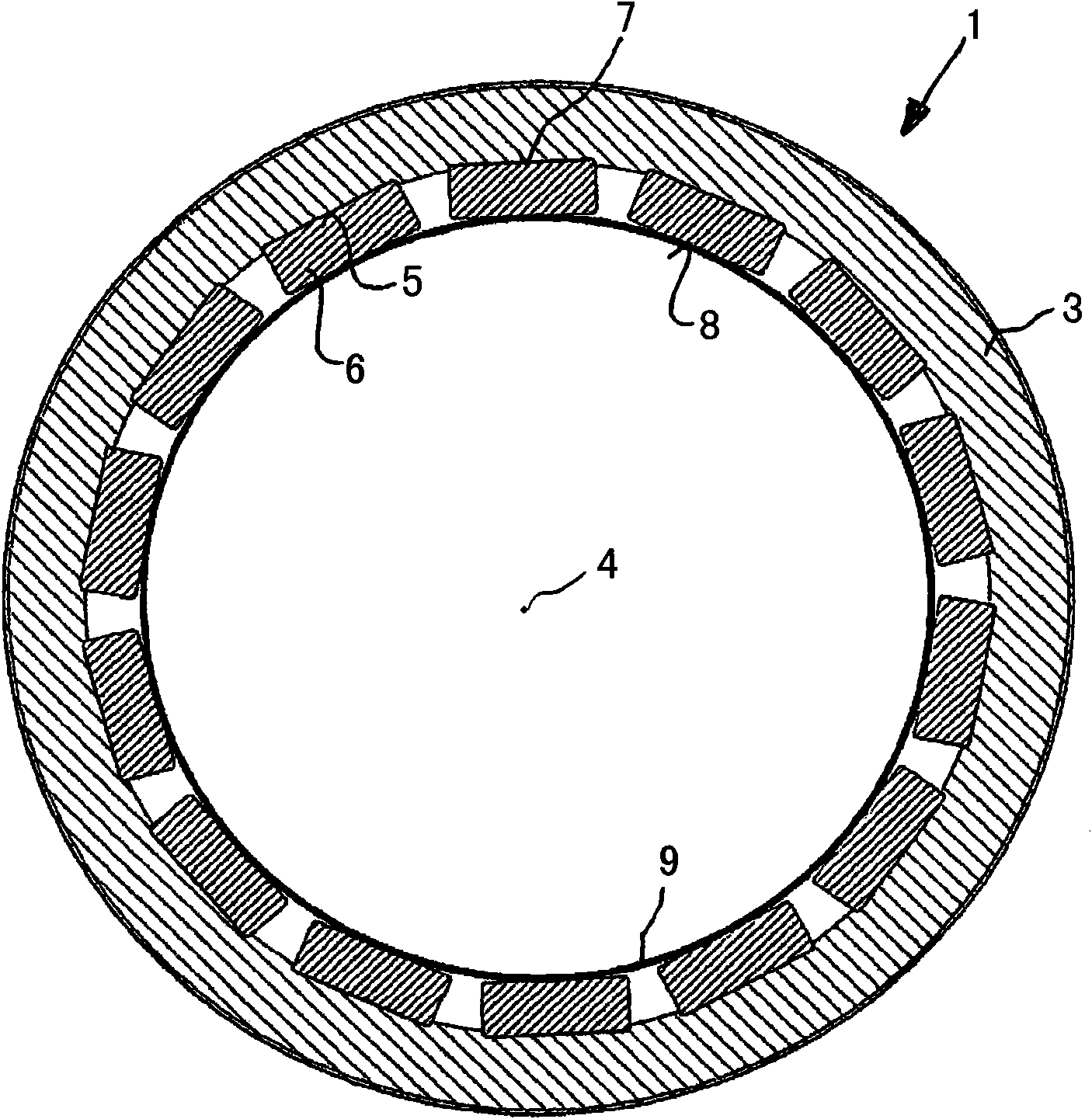
[0028]The outer part 1 of the magnetic coupling 2 consists of an annular outer support body 3, inside which there is a groove 5 arranged parallel to the longitudinal central axis 4, in which a magnet 6 is arranged. The magnets 6 are distributed on the inner periphery of the support body 3 via the slots 5 at equal intervals. The magnets 6 have a rectangular cross-section and are each seated in the slots 5 with their radially outwardly directed sides 7 . The inwardly directed side 8 of the magnet 6 , facing away from the side 7 , bears against the inner side of a housing inner wall 9 forming part of the housing which seals the magnet 6 . The housing inner wall 9 presses the magnet into the groove 5 by pretensioning. Due to the rectangular shape of the magnets 6 , an approximately linear arrangement parallel to the longitudinal center axis 4 results on the housing inner wall 9 .

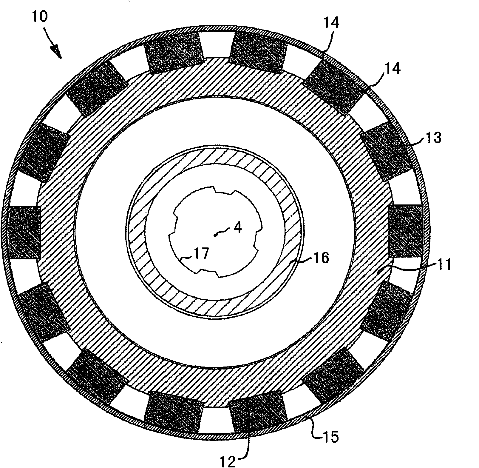
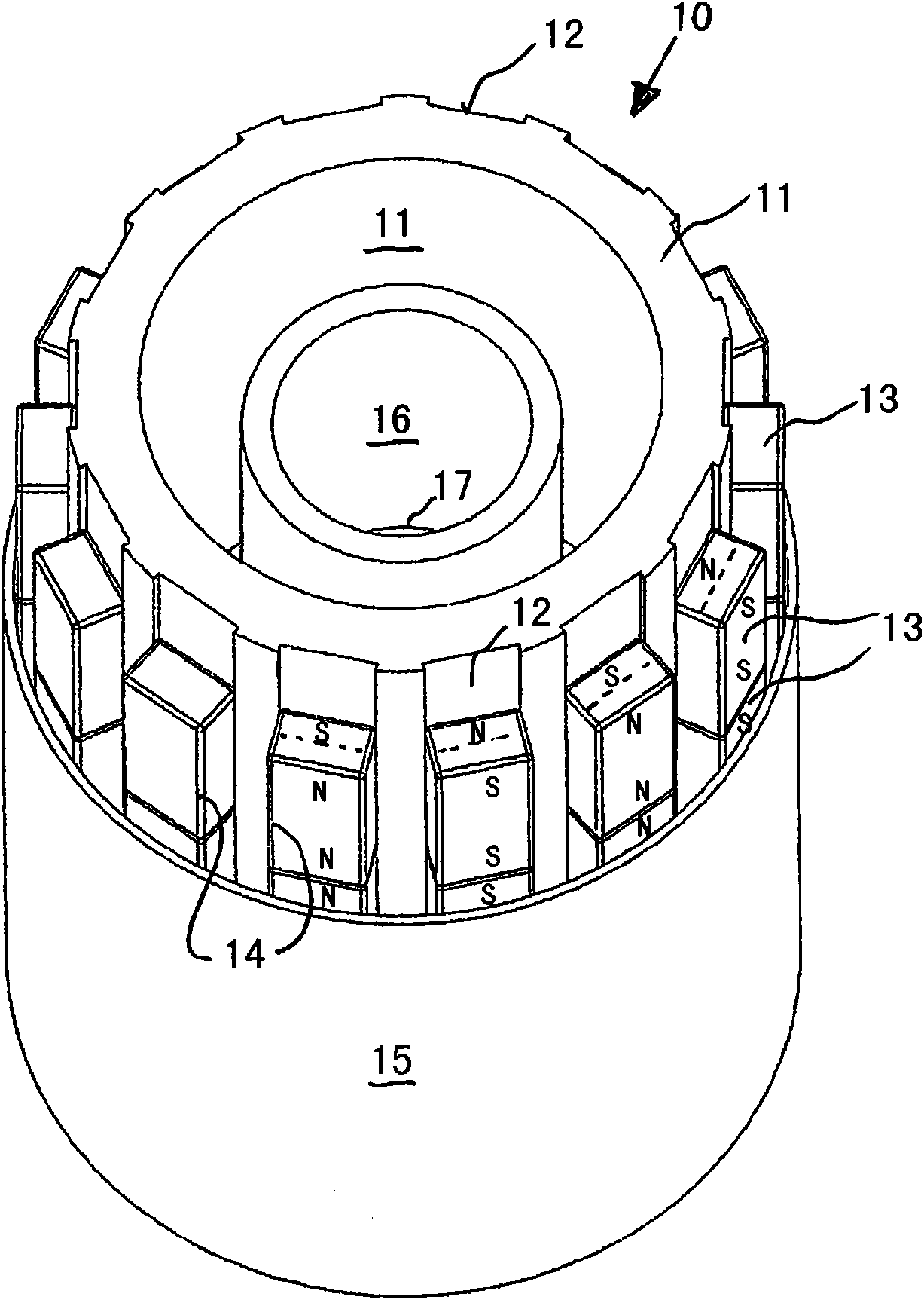
[0029] The inner part 10 of the magnetic coupling 2 has a support body 11 which is likewise annula...


PUM


Abstract

The invention relates to a magnetic drive arrangement comprising a plurality of permanent magnets (13) that are arranged along the periphery of the housing wall (15). Said magnets (13) are held in a positive-fit by the housing wall (15) and lie thereon. As a result, said arrangement can be produced in a simplified manner. Advantageously, parallelepiped magnets (13) can be used.

Description

technical field [0001] The invention relates to a magnetic drive having the features of the preamble of claim 1 . Background technique [0002] Magnetic drives of the type mentioned at the outset can be used for different purposes, e.g. as rotors in brushless DC motors or in magnetic couplings (magnetische Kupplung) in order to transmit, for example, the rotation of a drive shaft to a transmission shaft without contact superior. Such couplings are typically formed from an inner coupling part and an outer coupling part, which are each arranged separately in a preferably hermetically closed housing. In this case, the inner coupling part has an inner support body, which supports magnets distributed over its outer circumference, which are surrounded by a closed plate casing as a housing. The outer coupling part has an annular support body, which is provided with magnets on its inner side over the entire circumference and which is likewise surrounded by a sleeve-shaped housing....

Claims


Application Information

Patent Timeline
Patent Type & Authority Applications(China)
IPC IPC(8): H02K49/10F04D13/02
CPCF04D13/027H02K49/106
Inventor 黑尔格·格兰阿尔弗雷德·利斯博格·彼泽森
Owner GRUNDFOS MANAGEMENT AS
Learn More