A substrate integration waveguide multi-mode filter based on square high order cavity

A substrate-integrated waveguide and filter technology, which is applied in the high-frequency field, can solve the problems of inability to design and process, and the influence of metallized through holes is too large, and achieve the effect of improving acceptable tolerances.

Inactive Publication Date: 2008-07-09
SOUTHEAST UNIV
View PDF0 Cites 9 Cited by
  • Summary
  • Abstract
  • Description
  • Claims
  • Application Information

AI Technical Summary

Problems solved by technology

[0003] Technical problem: the purpose of the present invention is to propose a substrate integrated waveguide multimode filter based on a square high-order mode cavity, which solves the problem of the performance of the SIW main mode filter in the high frequency stage due to the too small cavity. It is

Method used


Image

  • A substrate integration waveguide multi-mode filter based on square high order cavity
  • A substrate integration waveguide multi-mode filter based on square high order cavity
  • A substrate integration waveguide multi-mode filter based on square high order cavity

Examples


Embodiment 1

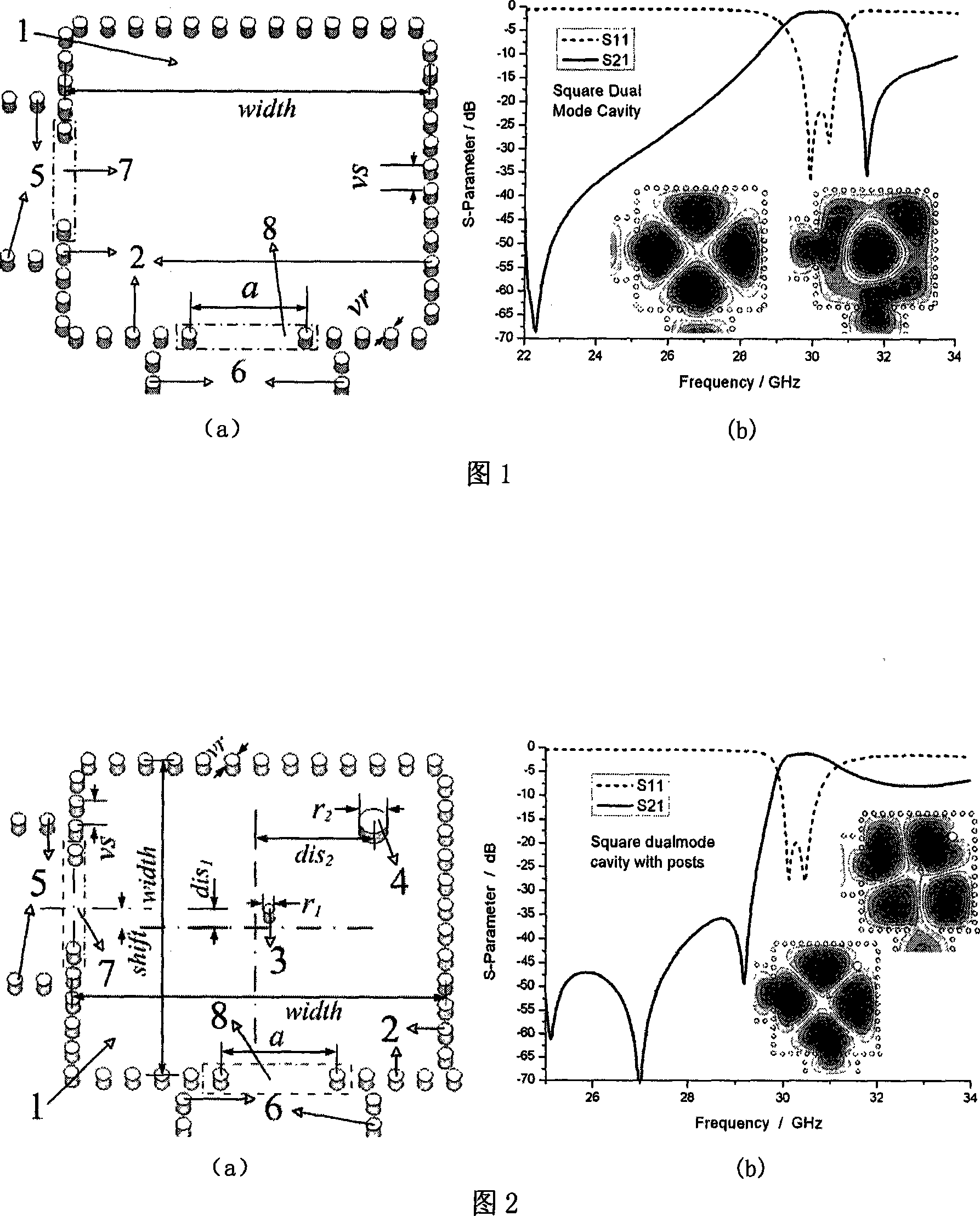
[0022] Embodiment 1 Q-band filter based on two square SIW dual-mode cavities

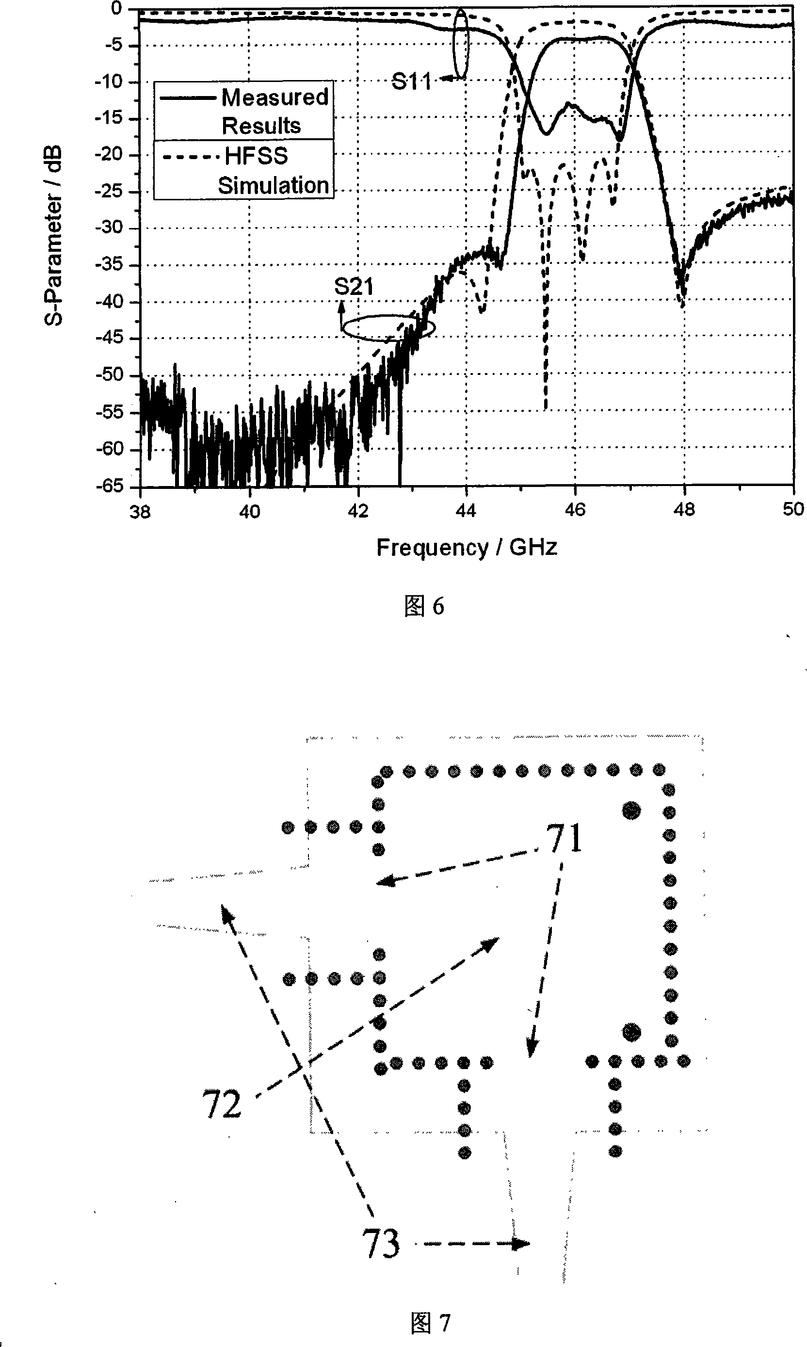
[0023] The physical structure of the filter design is shown in Figure 5. The dual-mode cavity 51 shown in FIG. 1 , the dual-mode cavity 52 shown in FIG. 2 , the microstrip feeder and its gradient line 53 for testing, and the metal copper 55 on the dielectric substrate. The size of a single substrate integrated waveguide dual-mode cavity is less than 7mm×7mm. The whole filter is composed of two different square dual-mode cavities folded, which is very small and compact. The substrate is made of Rogers5880 material with a dielectric constant of 2.2. The thickness is 0.254mm, and if a substrate with a higher dielectric constant is used, the cavity size will be further reduced. The measured transmission characteristics of the filter are shown by the solid line in Figure 6. The measured loss is about 4.38dB. This loss includes the loss caused by the test connector, microstrip feeder line and gradient li...

Embodiment 2

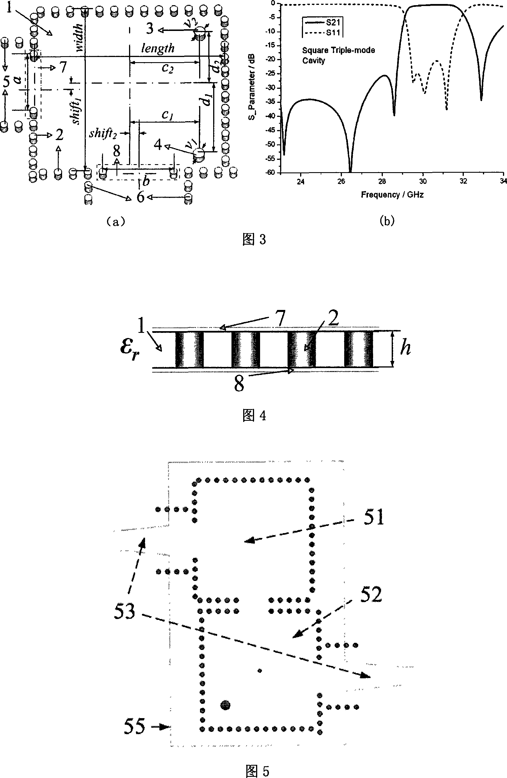
[0024] Embodiment 2 Q-band single-cavity three-mode filter

[0025] In order to verify the characteristics of the three-mode filter, a three-mode filter with a single square cavity is designed and realized, and the structure is shown in Figure 7. The input-output inductive window coupling 71, the three-mode cavity 72 shown in FIG. 3, the input-output microstrip feed and its gradient line 73 for testing. The cavity size is about 7mm×7mm, and the substrate is still made of Rogers5880 material with a thickness of 0.254mm and a dielectric constant of 2.2. In order to facilitate testing, the microstrip feeder is deflected at 90 degrees, and the entire three-mode cavity is realized by metal through holes, and the processing is very simple. The simulation and test response of the filter are shown in Figure 8. The test insertion loss of the filter is about 2.48dB, which has included the influence of the microstrip feeder and the test connector. The actual filter loss is about 1.1dB. T...

Embodiment 3

[0026] Embodiment 3 Q-band filter based on square three-mode cavity and circular dual-mode cavity

[0027] In Embodiment 3, a square three-mode cavity is applied to a two-cavity filter, and better performance is expected to be obtained. The physical structure of the filter is shown in Figure 9. The microstrip feed and gradient line 91 used for testing, the three-mode cavity 92 shown in FIG. 3 , and a circular dual-mode cavity 93 . The circular dual-mode cavity has a larger passband bandwidth and better upper sideband. The substrate used in the filter is Rogers5880 material with a thickness of 0.254mm and a dielectric constant of 2.2. Filters include microstrip and tapered lines, 50 ohm microstrip lines for testing, tapered lines for impedance matching, and a circular cavity and a square trimode cavity. The test results are shown in Figure 9. The filter test insertion loss is about 3.2dB. If the influence of connectors and microstrips is removed, the actual loss should be ab...


PUM

PropertyMeasurementUnit
Diameteraaaaaaaaaa

Abstract

The invention relates to a substrate integrated multi-mode filter which is based on a square high-order mode cavity, the upper surface and the lower surface of a medium substrate (1) are respectively coated with an upper surface metal (7) and a lower surface metal (8), a metalizing through hole array (2) penetrates the medium substrate (1), the upper surface metal (7) and the lower surface metal (8); a first inductive column (3) and a second inductive column (4) which can play the roles of regulating the eigenfrequency of different modes and coupling between the modes are positioned in a square cavity which is surrounded by the metalizing through hole array (2); a first metal column inductive window (7) and a second metal column inductive window (8) are respectively arranged on the adjacent two sides of the square cavity, the cavity can realize the coupling of the input and the output of energy by metal column inductive windows; a first metalizing through hole array (5) and a second metalizing through hole array (6) are respectively positioned at the first metal column inductive window (7) and the second metal column inductive window (8) to be corresponding to the input and the output of the cavity of the filter, which are connected with an external circuit.

Description

technical field [0001] The invention relates to a filter technology applied in the fields of millimeter-wave circuits, military and civilian communication systems, etc., this type of filter adopts a substrate integrated waveguide (Substrate Integrated Waveguide SIW) high-order mode square cavity and combines multi-mode technology, especially suitable for applications with high frequency, high performance and plane integration with the system. Background technique [0002] Traditional millimeter-wave filters usually use waveguide or microstrip line structures, but each of them has some insurmountable shortcomings. For planar structure filters such as microstrip or stripline, they have the advantages of small size and simple processing, but they have disadvantages such as low power capacity, large loss, and inconvenient sealing due to open structure, so they are only suitable for low frequency, power small circuitry. Waveguide filters have high power capacity, low loss, and ...

Claims


Application Information

Patent Timeline
IPC IPC(8): H01P1/207H01P1/20H01P5/08
Inventor 董元旦洪伟
Owner SOUTHEAST UNIV
Why Eureka
Try Eureka