
Fibre reinforced composite component

a composite component and fiber reinforced technology, applied in climate sustainability, application, air transportation, etc., can solve the problems of high cost of honeycomb core production, low tolerance to damage, and high production cos

Inactive Publication Date: 2006-03-23
SHORT BROTHERS
View PDF4 Cites 20 Cited by
  • Summary
  • Abstract
  • Description
  • Claims
  • Application Information

AI Technical Summary

Benefits of technology

[0004] The principal drawbacks that have been encountered with honeycomb sandwich panels are that (i) they are expensive to produce and (ii) they have a low tolerance to damage.
[0006] Because of their structural efficiency, honeycomb core stiffened panels have inherently thin skins, which can be easily damaged, are prone to water ingress and incur complex costly repairs.
[0008] It is an object of the present invention to provide a fibre reinforced composite component which does not have or which does not have to the same extent the drawbacks of high cost and low damage tolerance of the honeycomb sandwich panel construction.
[0022] (III) in a third processing stage the step of controlling the viscosity of the liquid resin in the sealed enclosure so that it is increased from the first viscosity value to bring the liquid resin to a cured state to form the fibre reinforced resin composite component.
[0024] The resin transfer infusion process makes it unnecessary to utilise prepreg elements in the component being manufactured and makes it advantageous for use in forming components which would otherwise be difficult to manufacture using traditional resin transfer mould equipment in which use is made of prepreg elements and involves the complications which arise out of the use of them.

Problems solved by technology

The principal drawbacks that have been encountered with honeycomb sandwich panels are that (i) they are expensive to produce and (ii) they have a low tolerance to damage.
The high costs are attributed to (i) the cost of producing the honeycomb core, (ii) the cost of machining and forming the panels, and (iii) the cost of manufacturing the required autoclaves, which are also labour intensive and utilise high cost raw materials such as pre-impregnated carbon fibre fabrics (prepreg).
Because of their structural efficiency, honeycomb core stiffened panels have inherently thin skins, which can be easily damaged, are prone to water ingress and incur complex costly repairs.

Method used


Image

  • Fibre reinforced composite component
  • Fibre reinforced composite component
  • Fibre reinforced composite component

Examples


Embodiment Construction

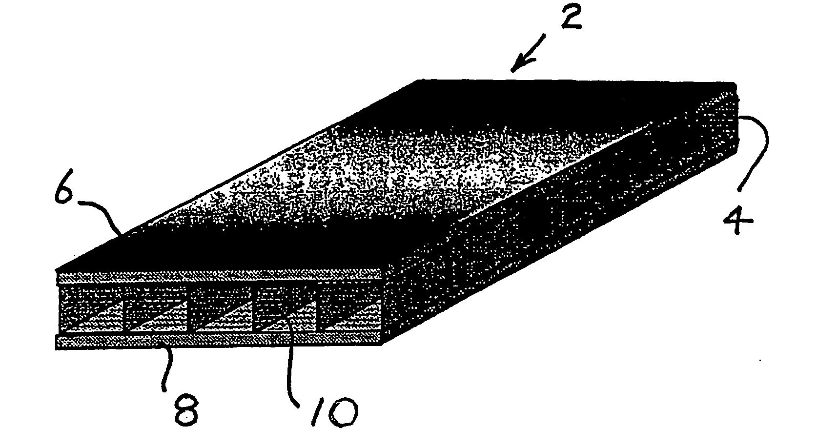
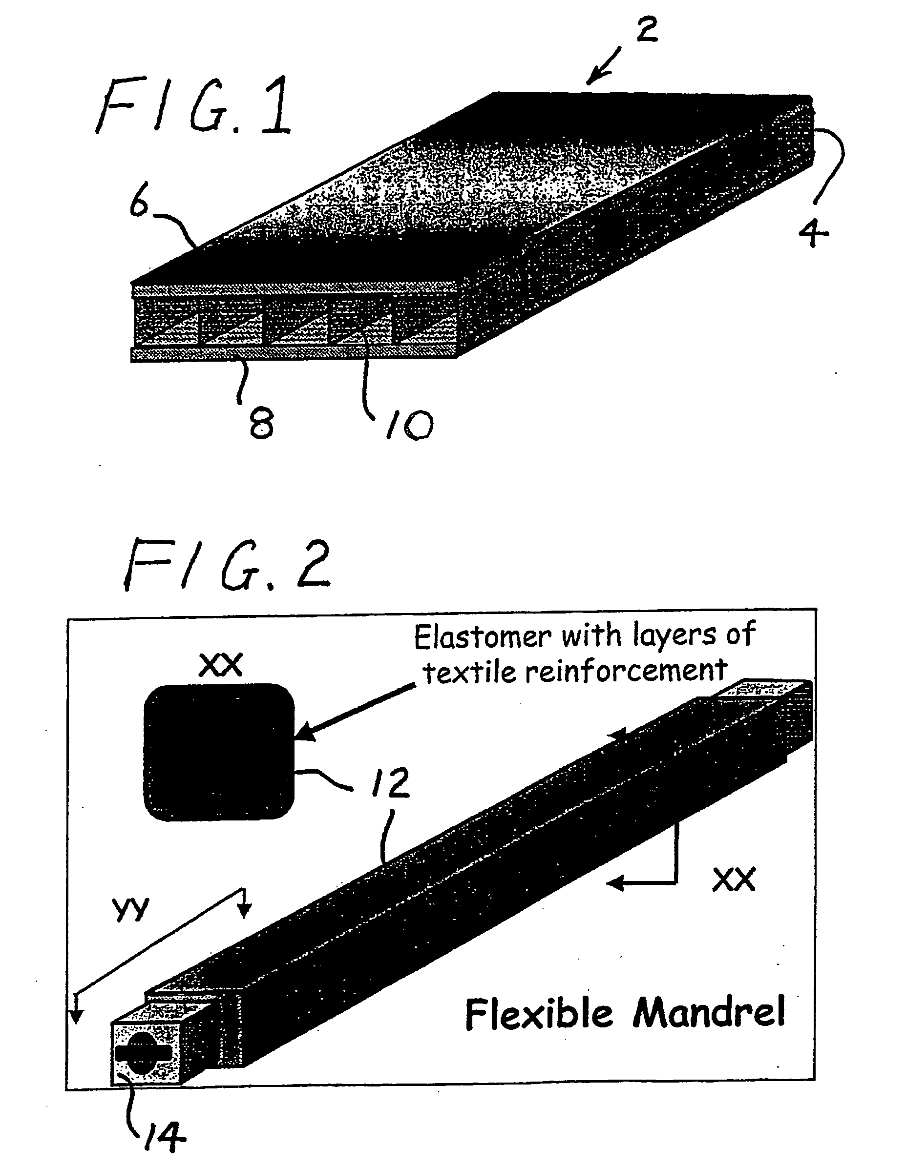
[0044] Referring to FIG. 1, a fibre reinforced composite panel component 2 according to the invention comprises a cell defining wall structure 4 located between front and rear skins 6 and 8. The wall structure 4 is in the form of cured fibre reinforced wall elements 10 which extend in side by side relation along the length of the component.

[0045] The following materials are suitable for producing both the wall structure 4 and the skins 6 and 8:

[0046] (i) Advanced composite materials.

[0047] (ii) Dry fabrics with multiple layers of uni-directional fibres stitched together.

[0048] (iii) Non-crimp fabrics (NCF) which utilise heavy weight tows.

[0049] In particular the following materials may be considered for both the wall structure 4 and the skins 6 and 8:

[0050] (i) Heavy uni-directional non-crimp fabric.

[0051] (ii) Biaxial non-crimp fabric.

[0052] (iii) Uni-weaves and 2D weaves (high tow count).

[0053] (iv) 2D braids.

[0054] (v) Triaxial braids, although these braids could have d...


PUM

PropertyMeasurementUnit
timeaaaaaaaaaa
lengthaaaaaaaaaa
widthaaaaaaaaaa

Abstract

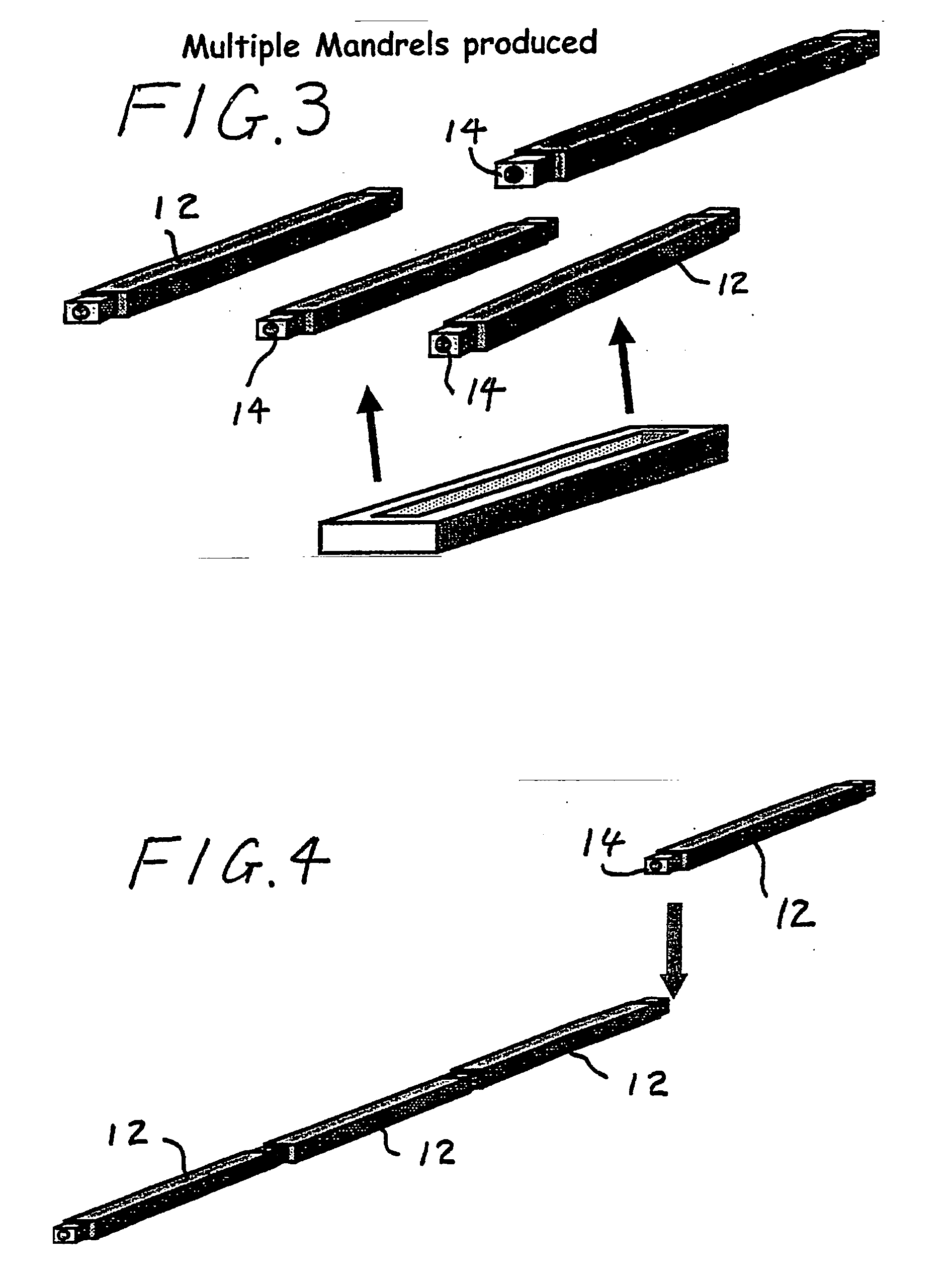
A fibre reinforced composite component is provided having cured fibre reinforced wall elements which extend in side by side relation along the length or width of the component between the front face and the rear face and which are formed by setting up an assembly of mandrels in side by side disposition, which are clad with a reinforcing fibre material, curing the material after resin impregnation to form the wall elements, and removing the mandrels to form cells bounded or partly bounded by the wall elements.

Description

[0001] This is a continuation application of International Application PCT / GB03 / 02458, having an international filing date of Jun. 7, 2003, now abandoned, which claims priority to UK Application GB 0213161.3, having a filing date of Jun. 7, 2002, for which priority under 35 U.S.C. 119 is claimed.BACKGROUND OF THE INVENTION [0002] The present invention relates to a fibre reinforced composite component and its manufacture. SUMMARY OF THE INVENTION [0003] Fibre reinforced composite components are particularly suitable for forming structural panels used in many industries including the aerospace industry. Typical examples of such panel structures are wing-to-fuselage fairings, stiffened skins of primary structures such as fuselages and pressure bulkheads, and turbofan engine nacelle fan cowl doors where extensive use has been made of honeycomb sandwich panels which are used to stiffen composite secondary structures. [0004] The principal drawbacks that have been encountered with honeycom...

Claims


Application Information

Patent Timeline
Patent Type & Authority Applications(United States)
IPC IPC(8): B32B3/20B29C70/44B29D24/00
CPCB29C70/443B29D24/004Y10T428/24744Y10T428/24562Y02T50/433Y02T50/40
Inventor WILSON, ROBERT SAMUEL
Owner SHORT BROTHERS
Learn More