High-pressure pump for a fuel injection system of an internal combustion engine

a technology of high-pressure pump and fuel injection system, which is applied in the direction of liquid fuel engine, machine/engine, positive displacement liquid engine, etc., can solve the problems of complicated sealing off from the high pressure in the pump work chamber, high manufacturing cost, and complicated high-pressure pump. , to achieve the effect of easy manufacturing of the fuel delivery course and low wear

Active Publication Date: 2008-04-29
ROBERT BOSCH GMBH
View PDF10 Cites 12 Cited by
  • Summary
  • Abstract
  • Description
  • Claims
  • Application Information

AI Technical Summary

Benefits of technology

[0006]The high-pressure pump of the invention has the advantage over the prior art that no separate valve housing for the inlet valve and thus no sealing off from the high pressure in the pump work chamber are necessary. For the housing part, the only additional part that must be made is the valve seat, which can be machined in a simple way from the inside of the cylinder bore. The valve member is introduced from the inside of the cylinder bore, with its shaft leading, and the closing spring is mounted from the outside of the housing part, diametrically opposite the cylinder bore, and joined to the shaft of the valve member.
[0005]One high-pressure pump known from German Patent Disclosure 197 29 790 A1 has at least one pump element, with a pump piston guided displaceably in a cylinder bore of a housing part of the high-pressure pump and driven in a reciprocating motion. In the cylinder bore, the pump piston defines a pump work chamber, into which the pump piston, in its intake stroke, aspirates fuel via an inlet valve, and from which the pump piston in its pumping stroke positively displaces fuel. The inlet valve has a pistonlike valve member, which is guided displaceably in a valve housing communicating with the housing part of the high-pressure pump. The valve member has a sealing face, with which it cooperates with a valve seat, embodied on the valve housing for controlling a communication of the pump work chamber with a fuel inlet. The valve member is urged in the closing direction toward the valve seat by a closing spring, disposed in the valve housing, and by the pressure prevailing in the pump work chamber, and is urged in the opening direction by the pressure prevailing in the fuel inlet. The fuel inlet discharges in the valve housing, and the valve housing together with the valve member and the closing spring forms a preassembled structural unit, which is inserted into the housing part of the high-pressure pump. Because of the separate valve housing, the high-pressure pump is complicated and thus expensive to manufacture and produce. Moreover, the valve housing covers the pump work chamber, so that between the housing part of the high-pressure pump and the valve housing, complicated sealing off from the high pressure in the pump work chamber is necessary.

Problems solved by technology

Because of the separate valve housing, the high-pressure pump is complicated and thus expensive to manufacture and produce.
Moreover, the valve housing covers the pump work chamber, so that between the housing part of the high-pressure pump and the valve housing, complicated sealing off from the high pressure in the pump work chamber is necessary.

Method used


Image

  • High-pressure pump for a fuel injection system of an internal combustion engine
  • High-pressure pump for a fuel injection system of an internal combustion engine
  • High-pressure pump for a fuel injection system of an internal combustion engine

Examples


Embodiment Construction

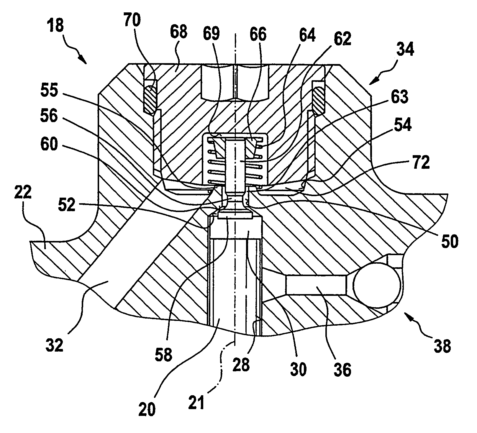
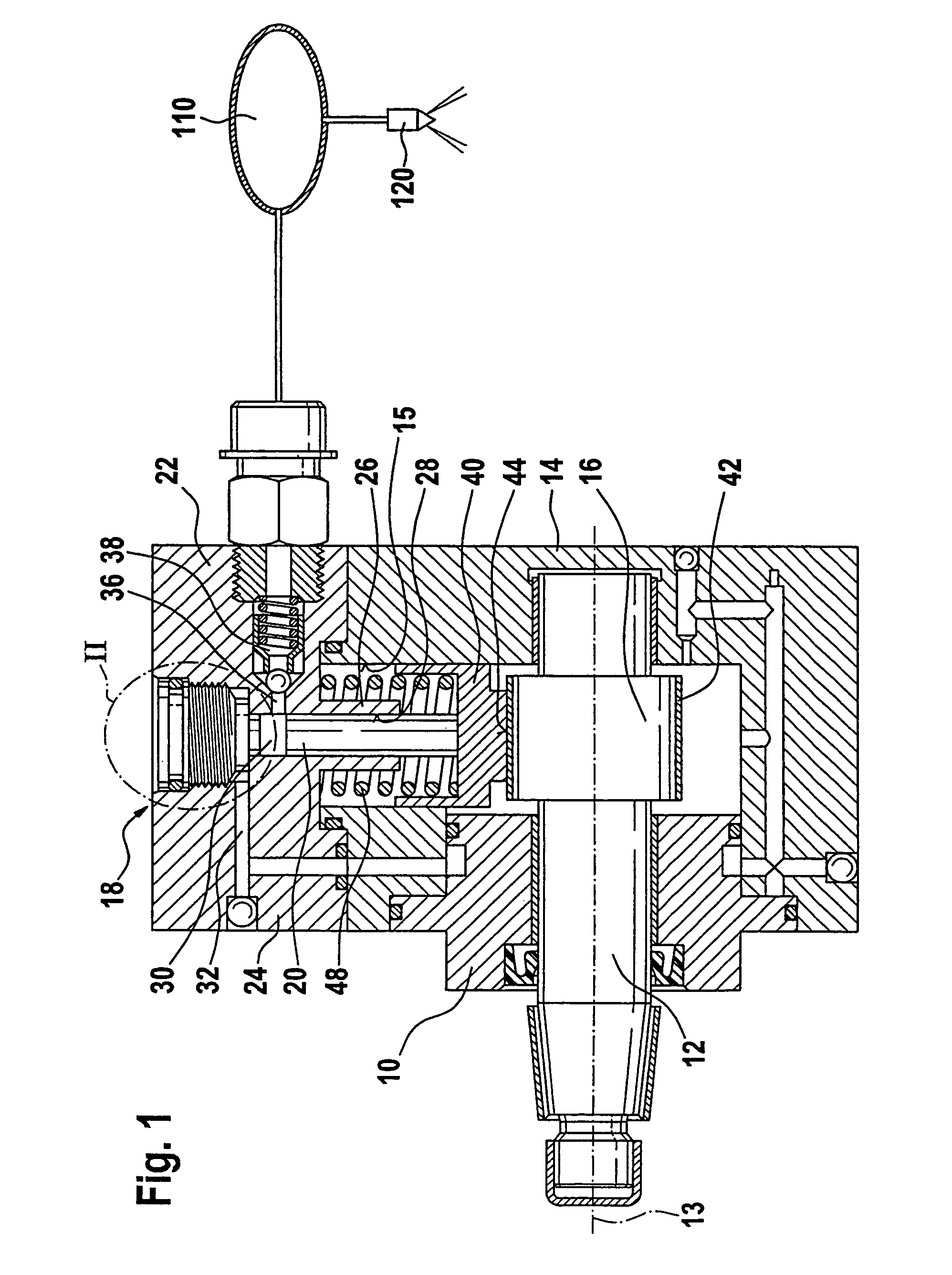
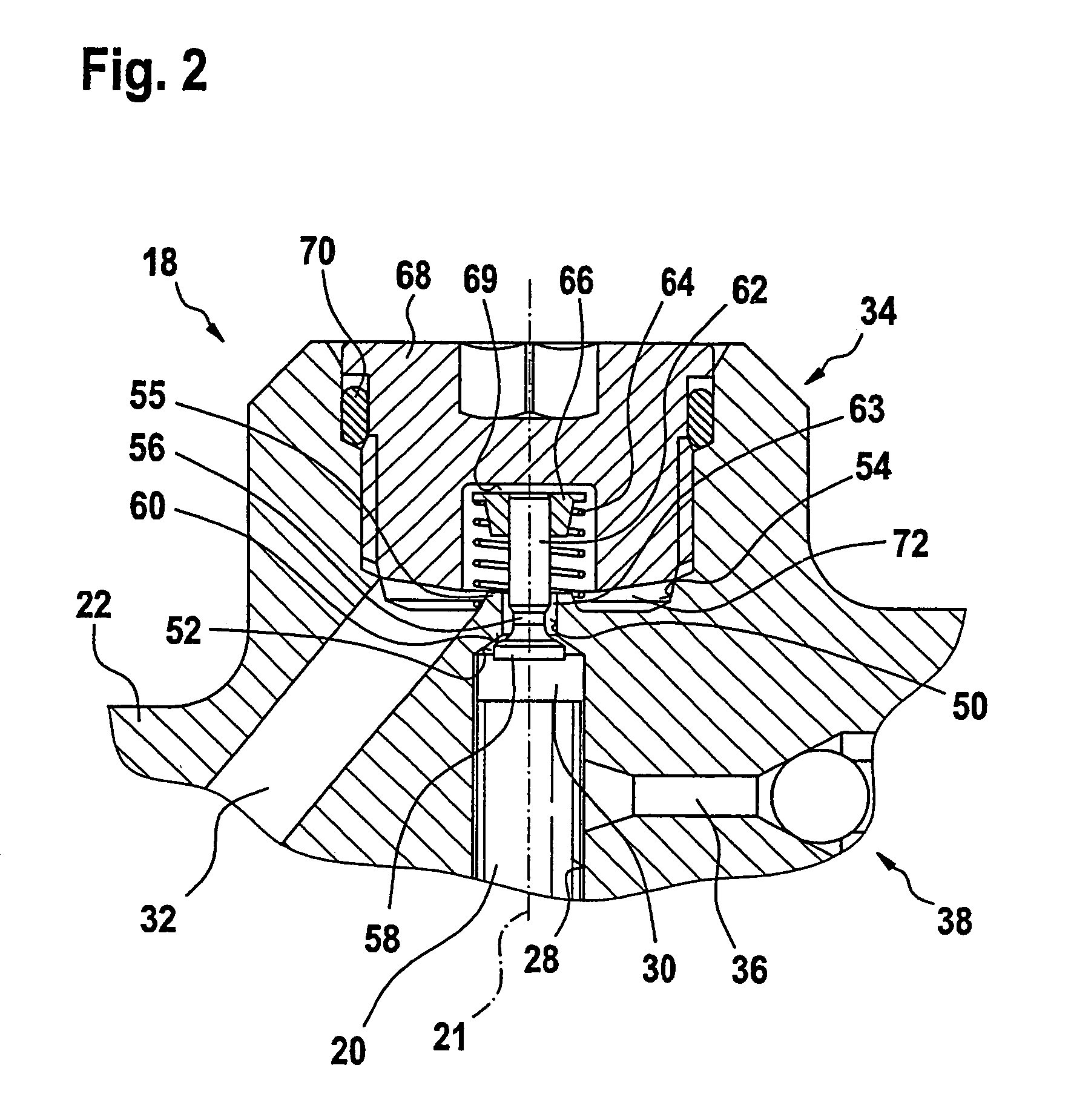
[0012]In the drawings a high-pressure pump for a fuel injection system of an internal combustion engine is shown which has a multi-part pump housing 10, in which a drive shaft 12, which can be driven to rotate by the engine, is rotatably supported. The drive shaft 12 is rotatably supported in a basic body 14 of the housing 10, via two bearing points spaced apart from one another in the direction of the pivot axis 13 of the drive shaft 12. The basic body 14 of the housing can in turn be embodied in multiple parts, and the bearing points may be located in different parts of the basic body 14. The basic body 14 comprises a material, especially lightweight metal, such as aluminum or an aluminum alloy, that has the requisite strength for supporting the drive shaft 12.

[0013]In a region located between the two bearing points, the drive shaft 12 has at least one portion 16, or cam, that is eccentric to its pivot axis 13; the cam 16 may also be embodied as a multiple lobe cam. The high-press...


PUM


Abstract

A high-pressure pump has at least one pump element, with a pump piston which is guided displaceably in a cylinder bore of a housing part of the high-pressure pump and is driven in a reciprocating motion and defines a pump work chamber in the cylinder bore, into which chamber fuel is aspirated via an inlet valve in the intake stroke of the pump piston. The inlet valve has a pistonlike valve member, which with a sealing face cooperates with a valve seat for controlling the communication of the pump work chamber with the fuel inlet. The valve member is disposed with a head, on which the sealing face is embodied, in the pump work chamber and protrudes out of the pump work chamber with a shaft adjoining the head. The valve seat is formed in the housing part at a transition from the cylinder bore to a bore of smaller diameter adjoining the cylinder bore. With its shaft, the valve member protrudes through the bore into a region of the housing part remote from the pump work chamber, in which region a closing spring is disposed that engages the shaft of the valve member.

Description

CROSS-REFERENCE TO RELATED APPLICATIONS[0001]This application is a 35 USC 371 application of PCT / EP2005 / 050193 filed on Jan. 18, 2005.BACKGROUND OF THE INVENTION[0002]1. Field of the Invention[0003]The invention is directed to an improved high-pressure pump for a fuel injection system of an internal combustion engine.[0004]2. Description of the Prior Art[0005]One high-pressure pump known from German Patent Disclosure 197 29 790 A1 has at least one pump element, with a pump piston guided displaceably in a cylinder bore of a housing part of the high-pressure pump and driven in a reciprocating motion. In the cylinder bore, the pump piston defines a pump work chamber, into which the pump piston, in its intake stroke, aspirates fuel via an inlet valve, and from which the pump piston in its pumping stroke positively displaces fuel. The inlet valve has a pistonlike valve member, which is guided displaceably in a valve housing communicating with the housing part of the high-pressure pump. T...

Claims


Application Information

Patent Timeline
Patent Type & Authority Patents(United States)
IPC IPC(8): F04B1/04F04B1/00F04B39/10F04B39/12F04B53/10F04B53/16
CPCF02M59/485F04B1/0452F04B53/102F04B53/1087F04B53/16F02M59/464
Inventor DUTT, ANDREASALEKER, JOCHEN
Owner ROBERT BOSCH GMBH
Why Eureka
Try Eureka