Affixing an anchor in a drilled hole

a technology for anchors and drilling holes, applied in the field of methods, can solve the problems of expensive manufacturing and difficult storage and handling

Active Publication Date: 2006-06-01
PATENT APPLIED TECH
View PDF12 Cites 20 Cited by
  • Summary
  • Abstract
  • Description
  • Claims
  • Application Information

AI Technical Summary

Benefits of technology

[0006] U.S. Pat. No. 6,484,471 describes the method of placing the adhesive on the anchor, thus eliminating the problems involved with mixing adhesives, usually consisting of two or more compounds, and after mixing, applying these adhesives into holes provided for the anchors. The arrangement shown herein, while useful under certain conditions, is expensive to manufacture and difficult to store and handle.

Problems solved by technology

The arrangement shown herein, while useful under certain conditions, is expensive to manufacture and difficult to store and handle.

Method used


Image

  • Affixing an anchor in a drilled hole
  • Affixing an anchor in a drilled hole
  • Affixing an anchor in a drilled hole

Examples


Embodiment Construction

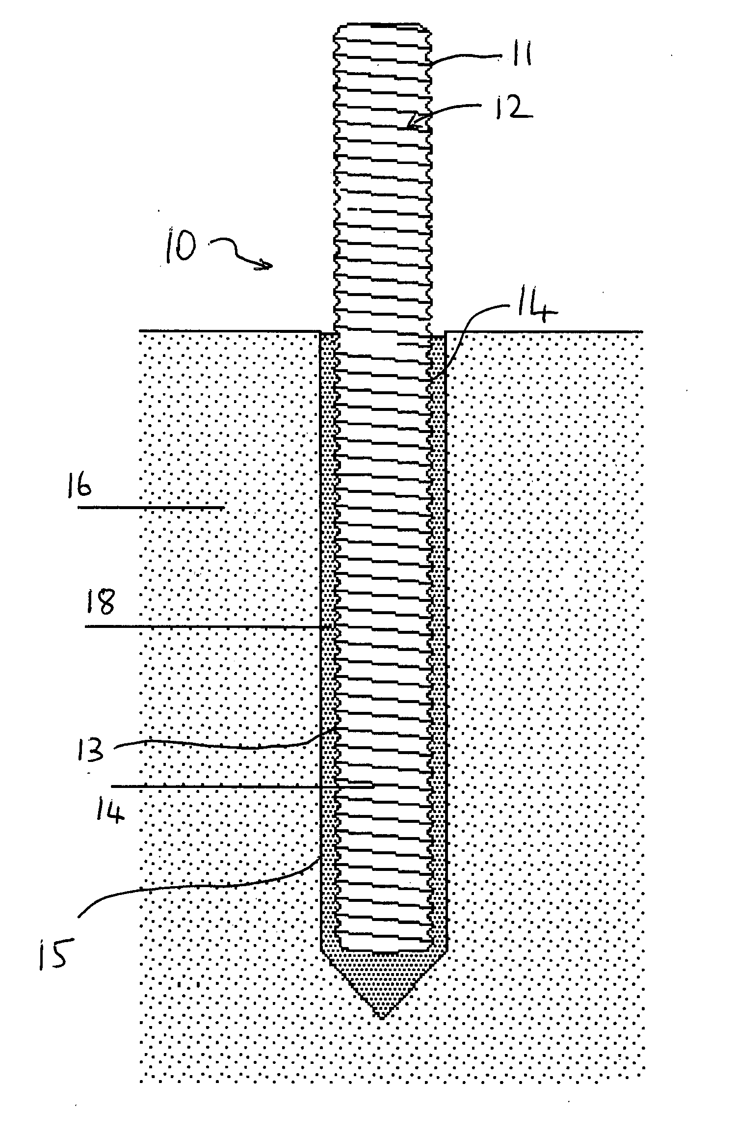
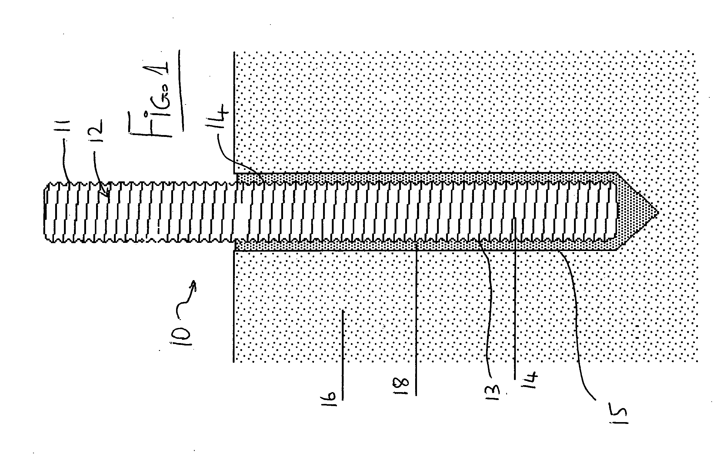
[0049] In FIG. 1 is shown an anchor body 10 in the form of a rod with external projections 11 in an upper portion 12 and projections 13 in a lower insert portion 14 arranged to be inserted into a drilled hole 15 in a body of concrete 16 or the material.

[0050] The projections 11 and 13 are formed in the embodiment shown as a continuous threaded section on the exterior of a rod. However other projections can be provided in many different arrangements as is well known to one skilled in the art.

[0051] The anchor 10 carries on its exterior surface a band 18 of an adhesive which has the character that it softens when heated and sets when it cools, such as a hot melt adhesive. Thus the band 18 is generally cylindrical where an inner surface 19 in contact with and engagement with the exterior surface of the rod so that it follows the shape of the surface with the projections 13. The band 18 has an exterior surface 20 which is generally cylindrical so as to approximately match the cylindri...


PUM

PropertyMeasurementUnit
frequencyaaaaaaaaaa
adhesiveaaaaaaaaaa
sizeaaaaaaaaaa

Abstract

An anchor is fastened into a drilled hole in substrate layer such as concrete by providing on an end portion of the anchor a surrounding layer of an adhesive of a character that it softens when heated and sets when it cools with a portion of the anchor exposed outside the hole. The exposed portion is heated by an inductive heating device in a heating cycle where the heating cycle is actuated by the operator switch but accurately controlled and limited to a single operation in the presence of the anchor by a control in the device in dependence on sensed environmental conditions and a measured size of the anchor.

Description

[0001] This application claims under 35 U.S.C. 119 the filing date of Provisional Application No. 60 / 630,655 filed Nov. 26, 2004 [0002] This invention relates to a method of and apparatus for affixing an anchor in a drilled hole. [0003] It is well known that such drilled holes can be formed in concrete or other materials but the field with which the present invention is concerned is primarily concrete anchors. [0004] The use of a setting or curing resin or other plastic material to bond an anchor into a drilled hole is known from a number of prior art documents. In particular U.S. Pat. No. 6,484,471 of the present inventors issued Nov. 26, 2002 discloses a method in which an anchor is inserted into a drilled hole with the anchor having a central core within which is a chemical which reacts with oxygen in an exothermic reaction to generate heat within the anchor to affect an adhesive material on the exterior of the anchor. [0005] It is known that the anchor itself may be formed of a ...

Claims


Application Information

Patent Timeline
Patent Type & Authority Applications(United States)
IPC IPC(8): B32B37/00E04F13/00E04B1/38
CPCE21D20/02F16B11/006F16B13/141E02D5/80F16B13/00F16B13/14
Inventor LANGTRY, DAVIDSTEED, WILLIAM G.
Owner PATENT APPLIED TECH
Why Eureka
Try Eureka