Hearing-aid anchoring element

a technology of anchoring element and hearing aid, which is applied in the direction of transducer casing/cabinet/support, electrical transducer, electrical apparatus, etc., can solve the problems of complicated fixture manufacturing procedure, and achieve low bone resorption, high manufacturing cost, and asymmetrical

Inactive Publication Date: 2006-06-15
OTICON
View PDF4 Cites 17 Cited by
  • Summary
  • Abstract
  • Description
  • Claims
  • Application Information

AI Technical Summary

Benefits of technology

[0023] The fixture of the present invention has a depth of the thread that is at least 10% of the maximum diameter of the threaded portion of the fixture. The depth of the threaded portion is however not greater than 20% of the maximum diameter of the thread of the fixture. By designing the depth of the thread in this interval, several significant and surprising advantages can be achieved for a fixture intended to be used for anchoring direct bone conduction hearing aids. The improvements are both on the microscopic and the macroscopic level. On a microscopic level, the increased surface offers an increased contact surface between the bone tissue and the fixture and this will contribute to a higher removal torque if forces directed to screw out the fixture from the bone is applied to the fixture when the fixture is osseointegrated. On a macroscopic level, the increased depth of the thread results in a firmer grip in the bone if trying to pull the fixture out of the hole.
[0042] In a preferred embodiment of the present invention the surface facing the threaded portion has multiple grooves. Multiple grooves may be more expensive to manufacture but will more safely ensure a low bone resorption under the flange.

Problems solved by technology

A thread deeper than this might also complicate the manufacturing procedure for the fixture.

Method used


Image

  • Hearing-aid anchoring element
  • Hearing-aid anchoring element
  • Hearing-aid anchoring element

Examples


Embodiment Construction

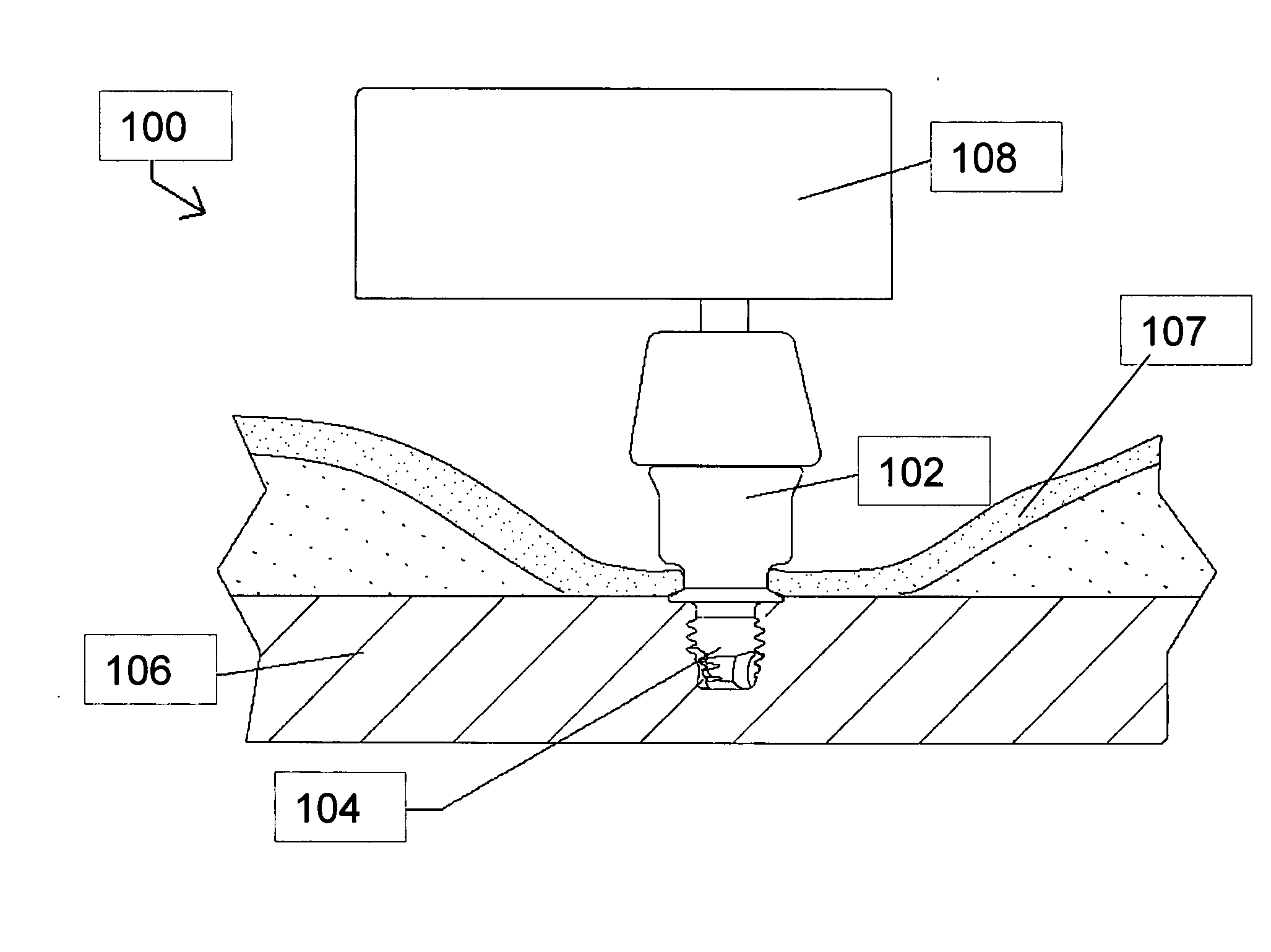
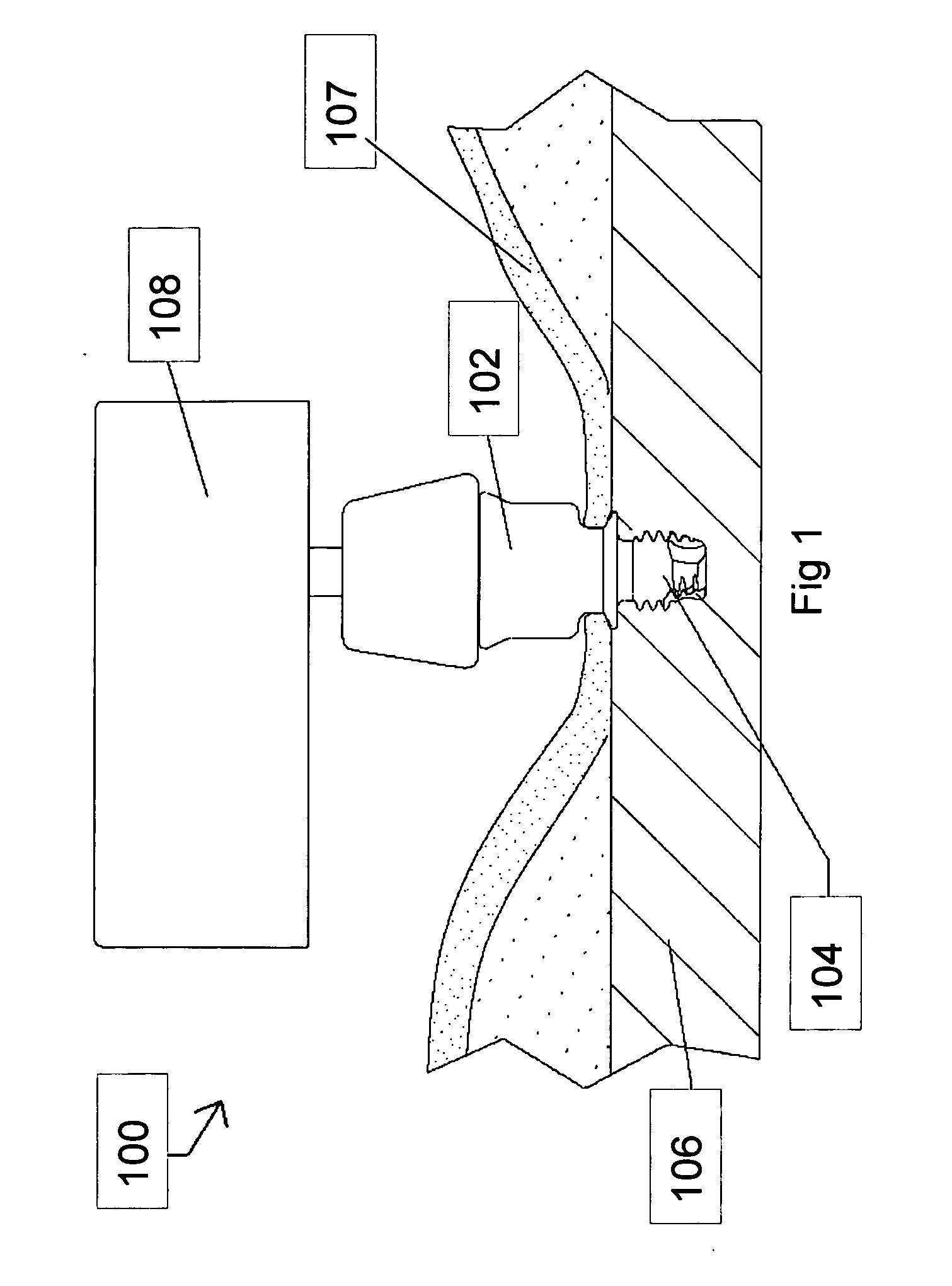
[0056]FIG. 1 is a side view of an illustrative example of a direct bone conduction hearing aid system 100 that has an abutment 102 with a fixture 104 that is screwed into a skull bone 106 of a user. A hearing-aid device 108 converts sound into vibrations and the vibrations is transferred to the skull bone 106.

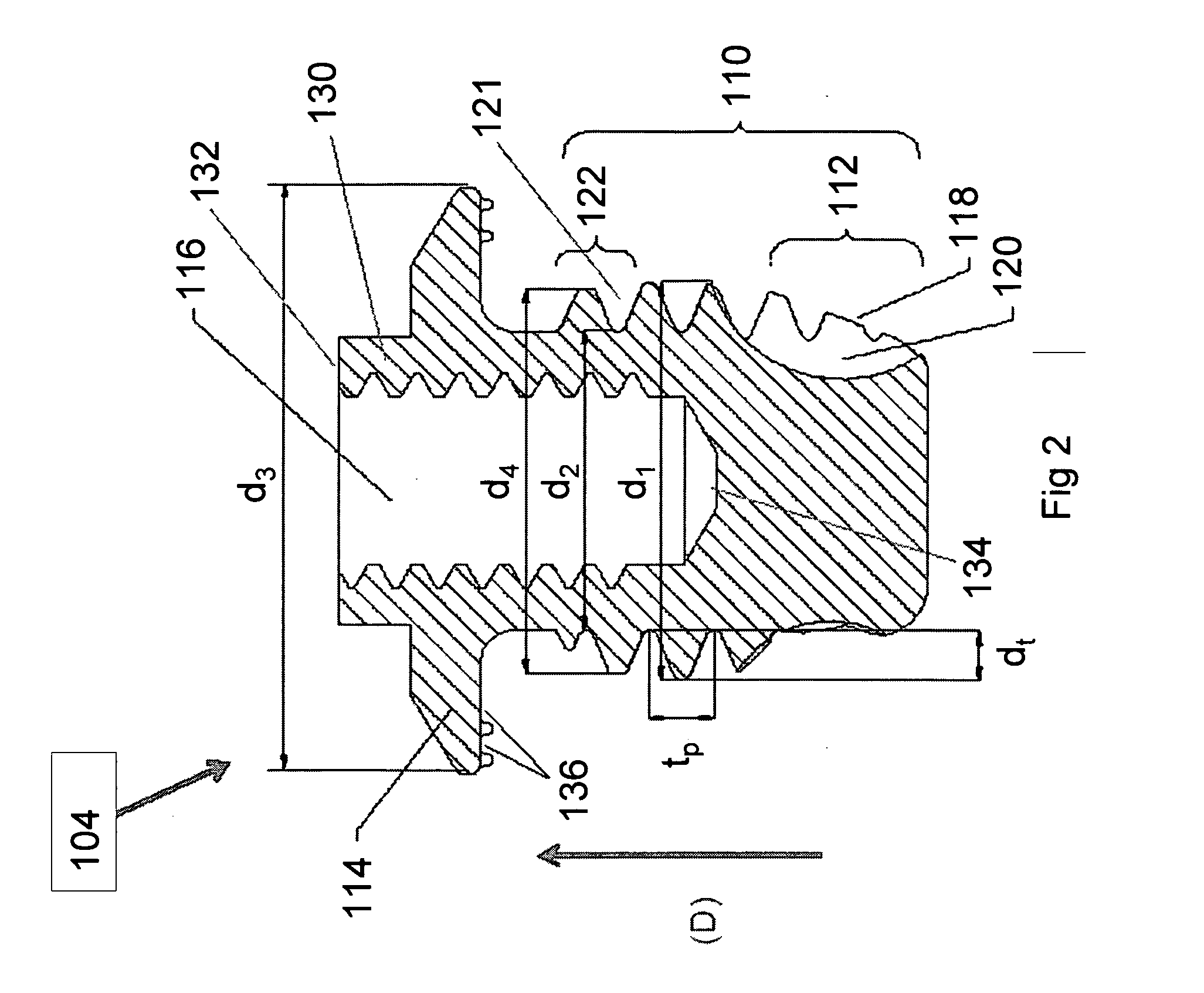
[0057]FIG. 2 is a cross-sectional side view and FIG. 4 is a perspective view of a preferred embodiment of the fixture 104. The fixture 104 has a threaded portion 110 having a maximum outer diameter d1 and an inner diameter d2. The thread has a depth dt and a thread pitch tp. The fixture has a conical outer portion 112 to facilitate the insertion of the fixture 104 into a hole in the skull bone 106.

[0058] An upper end of the fixture 104 has a radially outwardly protruding flange 114 with a diameter d3 to prevent the fixture 104 from being pushed into the skull. Preferably, the diameter d3 is greater than the diameter d2. An axial extension 130 has an axial threaded inner hole ...


PUM


Abstract

An anchoring system for anchoring a percutaneous attachment for a direct bone-conduction hearing-aid or an outer ear prosthesis to the skull bone, comprising a fixture portion, the fixture portion having a threaded portion. A flange is disposed at one end of the fixture portion. The flange has a surface facing the threaded portion and on this surface there is at least one groove to prevent bone resorption under the flange. The groove extends at least one turn on the side of the flange facing the threaded portion.

Description

PRIOR APPLICATION [0001] This is a continuation-in-part application based on U.S. patent application Ser. No. 10 / 981,340, filed 4 Nov. 2004.TECHNICAL FIELD [0002] The present invention relates to an anchoring system for anchoring a percutaneous attachment for a direct bone-conduction hearing-aid or an outer ear prosthesis to the skull bone. BACKGROUND OF THE INVENTION [0003] Bone conduction hearing aids are essential for the rehabilitation of patients suffering from hearing losses for which traditional hearing aids are insufficient. Direct bone conduction hearing aids have a vibrating transducer that transmits vibrations directly to a fixture anchored in the bone, i.e. the skin does not take part in the transmission of the vibrations from the vibrator to the fixture in the bone. The most common type of such devices consists of an external hearing aid with a vibrating transducer which, through a coupling, is connected to a skin-penetrating abutment that has an interconnection to a sc...

Claims


Application Information

Patent Timeline
Patent Type & Authority Applications(United States)
IPC IPC(8): H04R25/00
CPCH04R25/606
Inventor WESTERKULL, PATRIK
Owner OTICON
Why Eureka
Try Eureka