Door Closer

a technology for doors and windows, applied in door/window fittings, multi-purpose tools, construction, etc., to achieve the effect of avoiding damage or destruction of dampers, and facilitating exchang

Inactive Publication Date: 2012-05-17
DORMA GMBH & CO KG
View PDF43 Cites 20 Cited by
  • Summary
  • Abstract
  • Description
  • Claims
  • Application Information

AI Technical Summary

Benefits of technology

[0014]Another embodiment of the invention provides that the damper effect be produced by an eddy-current brake or a hysteresis brake.
[0015]In a preferred embodiment, within the cylinder, the piston may move gas or fluid between the two pressure compartments. Thus, small and standardized structural components can be utilized, which are inexpensive, easy to exchange and can be combined with each other to provide different damping power. The damper is thus self-contained, because all the structural components relevant for the damping function are incorporated within the damper. No leakages at the door closer will occur with the aforementioned embodiment. Blocked valves and blocked hydraulic lines will no longer occur, because they are not required for the damping function. And in case of re-mounting, the door closer does not have to be filled with oil either.
[0016]In one embodiment an overload protection is disposed at the abutment. Damage or destruction of the dampers is thereby avoided. In a preferred embodiment, the overload protection is configured as a leaf-spring, which deforms at too important forces.

Problems solved by technology

Also, the expensive manufacturing of the housing with incorporated channels and valves is no longer required.

Method used


Image

  • Door Closer
  • Door Closer
  • Door Closer

Examples


first embodiment

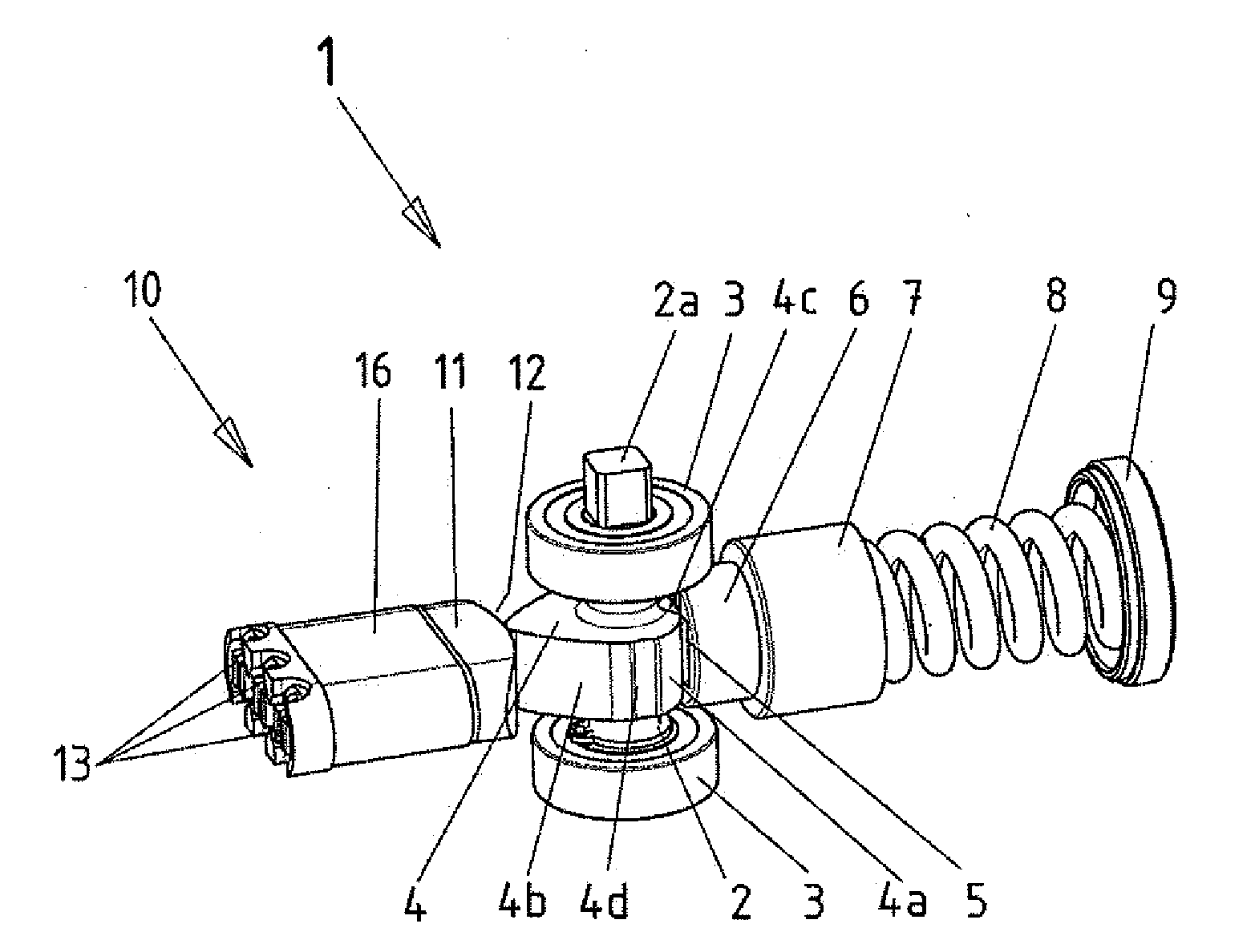
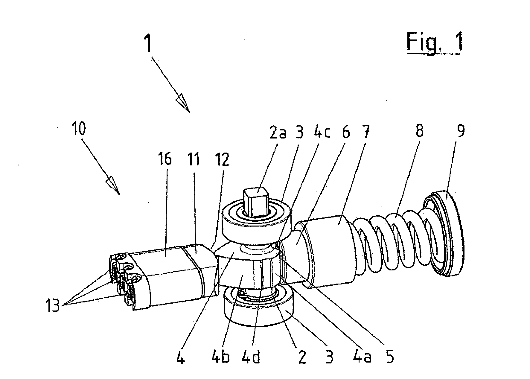
[0027]The one or more dampers 13, according to this first embodiment according to FIG. 1, is / are disposed in a damper cartridge 10, which has a damper reception 16 and an abutment 11 with an abutment surface 12, wherein the abutment surface 12 cooperates with the cam 4. The damper reception 16 may receive at least one or more dampers 13, wherein, in a preferred embodiment, the cylinders 15 of the dampers 13 are coated with plastic material or encased therein. The abutment 11 is connected to the pistons 14 of the dampers 13. The abutment 11 may have a flat, convex or concave abutment surface 12, which cooperates with the second running surface 4b of the cam 4. In this case, the geometry of the abutment surface 12 depends on the desired damping effect. As the dampers 13 function as closing dampers, the abutment 11 needs to be pressed against the cam 4 against the damping force. This is accomplished by means of one or more springs 17, which press the abutment surface 12 against the sec...

second embodiment

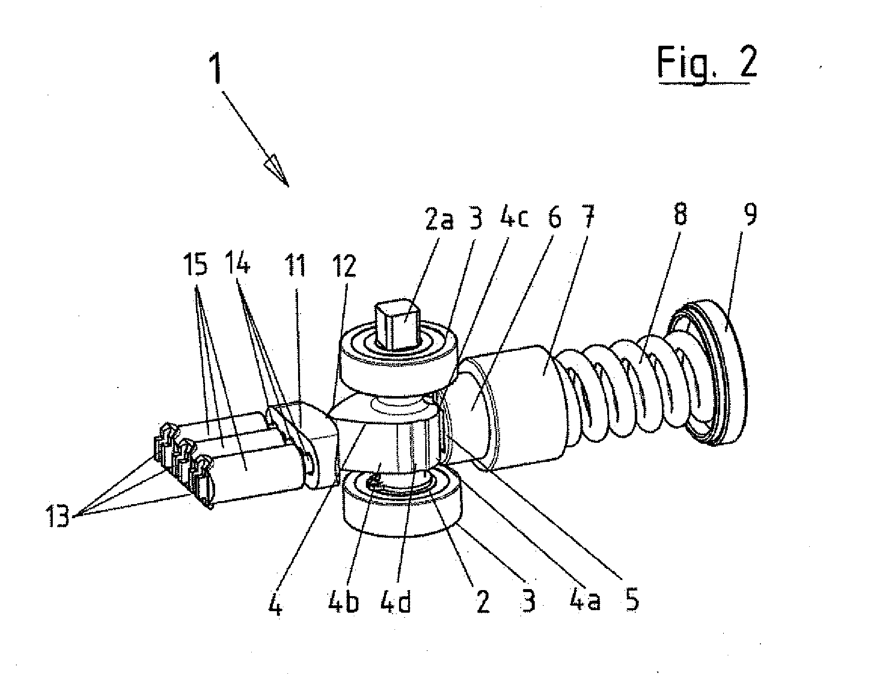
[0029]In the second embodiment according to FIG. 2, at least one damper 13 is disposed within the door closer 1, and comprises a piston 14 and a cylinder 15. In this embodiment, three dampers 13 are disposed next to each other, the pistons 14 thereof being connected to the abutment 11. In this case again, mounting / dismounting the dampers 13 is realized in that a non-illustrated closure, which is disposed at the frontal side of the door closer housing, is opened respectively closed, such as to be able to completely insert the one or more dampers 13 which are completely pre-mounted with the abutment 11. In this embodiment, unlike in the prior-art, in this case, no oil can leak from the door closer 1, because the damping medium, in case of a hydraulic or pneumatic damper 13, is encapsulated within the individual dampers 13. Therefore, soiling or clogging the hydraulic lines and valves is no longer possible. Just as no leakage will occur any more, which would be very unpleasant for the ...


PUM


Abstract

A door closer including a rotating shaft coupled to a door leaf, including a cam disposed on the rotating shaft in a torque-proof manner and cooperates with a spring-loaded roller, such that, when opening or closing the door leaf, the roller rolls on a first running surface of the cam, and in that a second running surface of the cam cooperates with a damping device. The damping device consists of at least one pre-mounted damper which is self-contained and is insertable into the door closer.

Description

CROSS REFERENCE TO RELATED APPLICATION[0001]This is a U.S. national stage of application No. PCT / EP2010 / 004304, filed on 15 Jul. 2010. Priority is claimed on German, Application No. 10 2009 034 742.9, filed 24 Jul. 2009, the content of which is incorporated here by reference.BACKGROUND OF THE INVENTION[0002]1. Field of the Invention[0003]The invention relates to a door closer including a rotating shaft coupled to a door leaf and a cam, which is disposed in a torque-proof manner on the rotating shaft and cooperates with a spring-loaded roller, such that, when opening or closing the door leaf, the roller rolls on a running surface of the cam.[0004]2. Detailed Description of Prior Art[0005]The document DE 9209276 U1 describes a door closer including a damping device. This damping device affects the opening and closing behavior of the swing leaf door and acts upon the cam disc located on the opposite side of the spring-loaded pressure roller. This damper is configured as a hydraulic pis...

Claims


Application Information

Patent Timeline
Patent Type & Authority Applications(United States)
IPC IPC(8): E05F3/10E05F3/20
CPCE05F3/104Y10T16/281Y10T16/304E05Y2900/132E05Y2800/21
Inventor WALHORN, OLIVER
Owner DORMA GMBH & CO KG
Why Eureka
Try Eureka