Fluid-dispensing head for a 3D printer

a printing head and 3d printer technology, applied in the field of additive manufacturing systems, can solve the problems of sacrificing high resolution and prior designs that are not optimal, and achieve the effects of improving flexibility, avoiding excessive weight, size or structural complexity, and facilitating operation

Active Publication Date: 2014-08-28
CEL TECH
View PDF10 Cites 103 Cited by
  • Summary
  • Abstract
  • Description
  • Claims
  • Application Information

AI Technical Summary

Benefits of technology

[0020]A fluid-dispensing head according to the invention provides for two nozzles that can be readily switched into operation for improved flexibility, without excessive weight, size or structural complexity. Providing large and small nozzles can readily be swapped, allows the nozzles to be selected as required for maximum speed and resolution, for instance, by using the small nozzle to accurately produce exposed finished surfaces and the large nozzle for bulk infill. By proving a single rocker that controls both nozzle position and nozzle actuation, a simple, reliable, compact and lightweight mechanism is also provided.

Problems solved by technology

However, prior designs have not been optimal, and there is a need for a printer head with improved flexibility, which is not compromised by excessive weight, size or structural complexity.
However, it has previously been considered that high resolution must be sacrificed in using this technology in order to obtain reasonable operating speeds.

Method used


Image

  • Fluid-dispensing head for a 3D printer
  • Fluid-dispensing head for a 3D printer
  • Fluid-dispensing head for a 3D printer

Examples


first embodiment

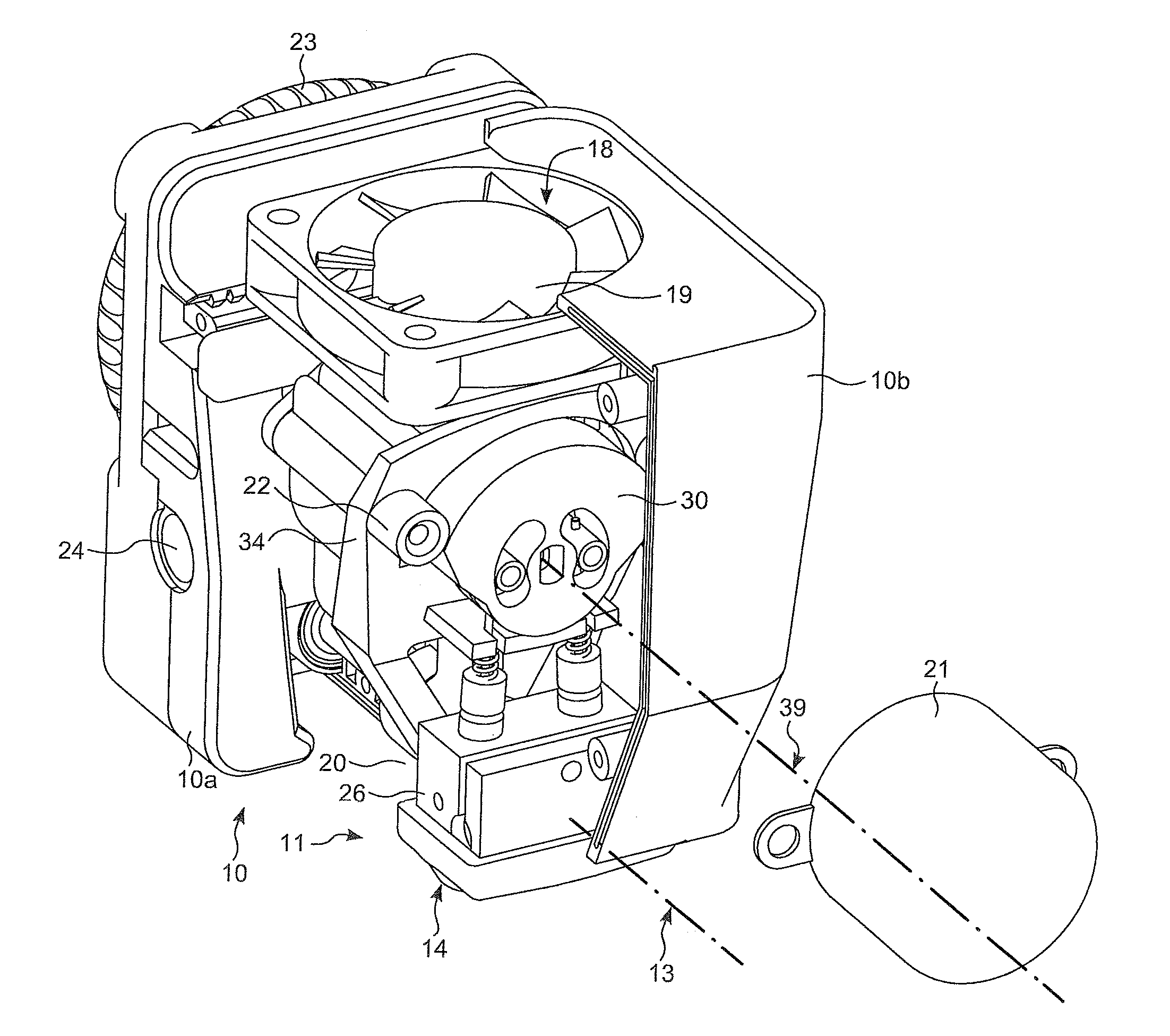
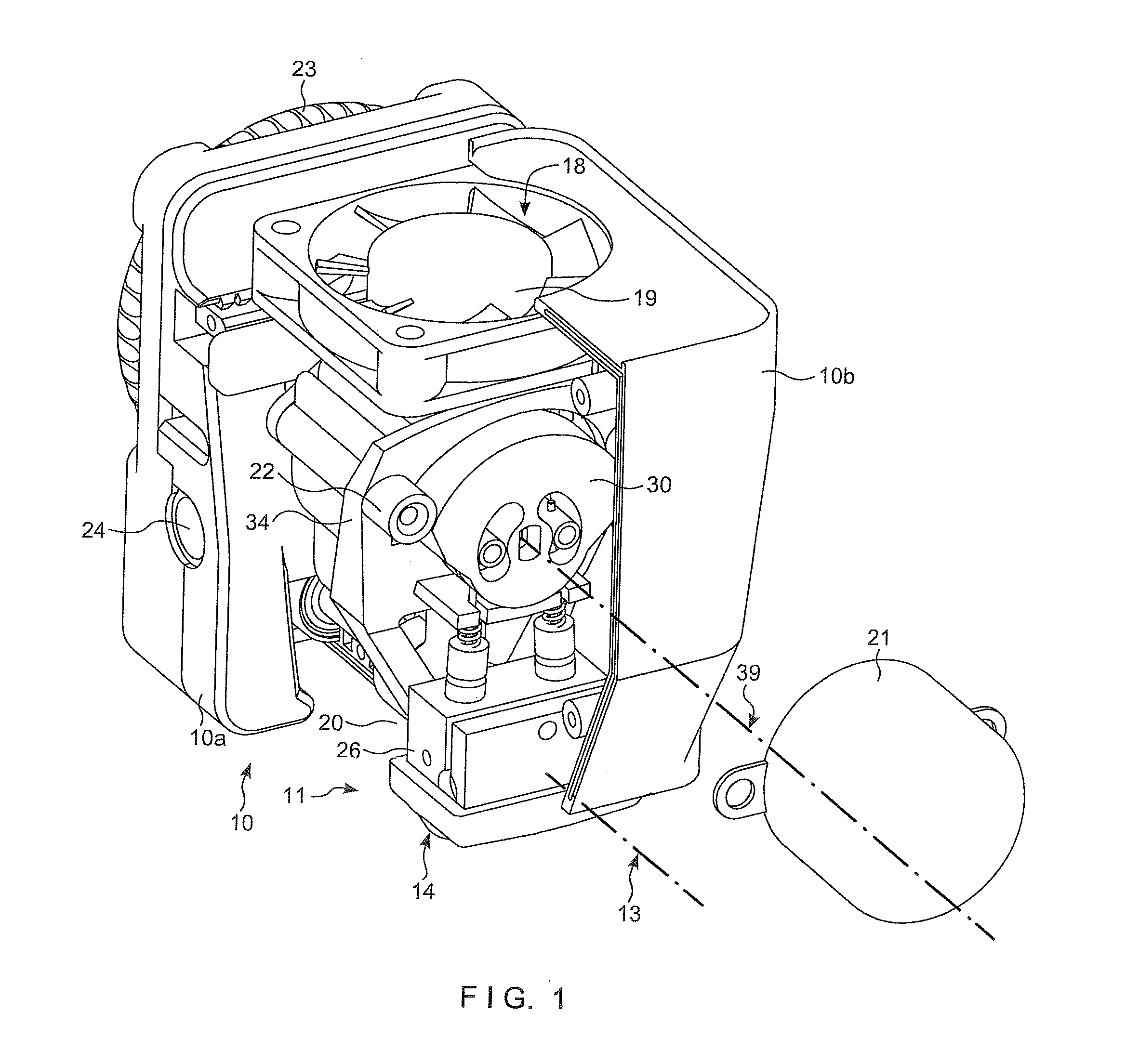
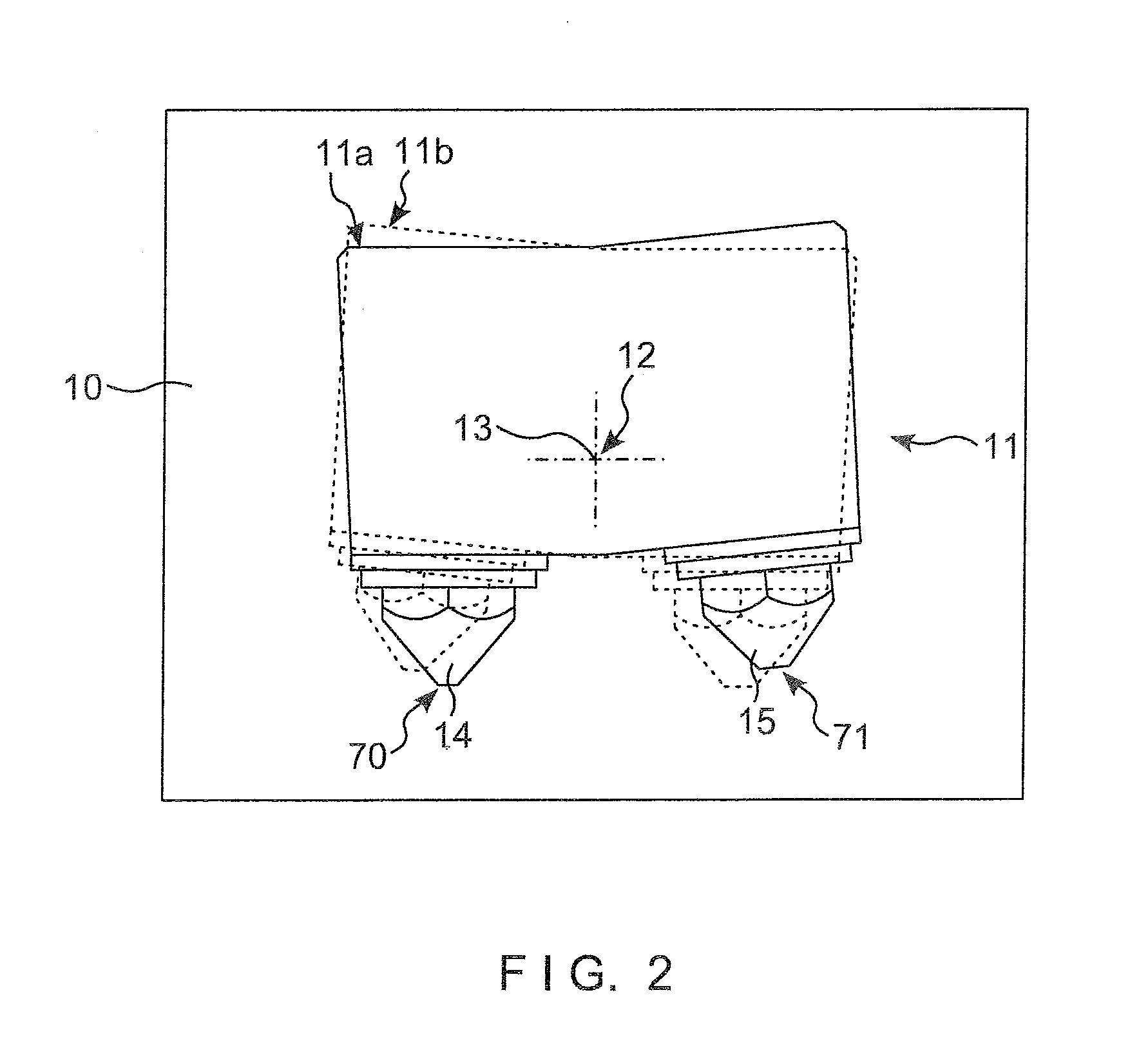
[0031]The present disclosure is directed to a print head assembly for use in an extrusion-based 3D printer and in FIGS. 1 to 4 a first embodiment is shown. Referring to FIGS. 1 and 2 of the drawings, the print head assembly generally comprises a structural support assembly or support 10 to which a fluid-dispensing head 11 may be coupled by a pivot 12, allowing the fluid-dispensing head 11 to rotate about a pivot axis 13, relative to the support 10. The fluid-dispensing head 11 includes a manifold 26 which may be fixed to the pivot 12 and to which are mounted first and second nozzles 14, 15.

[0032]The fluid-dispensing head 11 generally pivots between a first position indicated by 11a and a second position indicated by 11b and shown in dashed outline in FIG. 2. In position 11a the first nozzle 14 is in its nozzle-operating position in which flowable material may be dispensed, and its outlet 70 extends below the outlet 71 of the second nozzle 15 to ensure that the unused second nozzle i...

second embodiment

[0042]FIGS. 10 and 11 illustrate the construction of the pivot 112 of the second embodiment which supports the fluid-dispensing head 111 in bearings 127 engaging a shaft portion of the pivot 112. The bearings 127 may be fixed between the housing shells 10b of the support 10 and allow the pivot 112 to turn about axis 13. The pivot 112 includes two passages 128, 228 along which two consumable filaments (not shown) may be fed to the melt chamber 63 of the manifold 126. The passages 128, 228 may be arcuate and generally symmetrically disposed either side of an plane bisecting the pivot 112. A neck 47 passing through the air gap 46 may be formed in the pivot 112 by a thin wall section of each of the passages 128, 228 providing a thermal bridge separating the manifold 126 from the mounting member 134.

[0043]Adjustable stops limiting the angular positions 11a, 11b are provided by two dog point set screws 65, one on each of the housing shells 10b, 10c which engage with magnets 66 fixed at th...


PUM

PropertyMeasurementUnit
perimeteraaaaaaaaaa
perimeteraaaaaaaaaa
sizesaaaaaaaaaa

Abstract

A head assembly for an extrusion-based 3D printer includes: a fluid-dispensing head having a manifold and at least two fluid-dispensing nozzles, of different sizes, which are mounted in communication with a melt chamber in a manifold. Outlets of each nozzle are closed by respective valve members. A rocker serves both to pivot the nozzles to their lowermost nozzle-operating position and to actuate the valve members, for ready switching between the valves, such that the smaller nozzle can be used for high resolution work, and the larger nozzle can be used for bulk infill.

Description

TECHNICAL FIELD[0001]The present invention generally relates to additive manufacturing systems for building three-dimensional (3D) parts in a layer-by-layer manner, also known as 3D printers. The invention particularly relates to printing heads used in 3D printers for extruding a flowable part material.BACKGROUND OF THE INVENTION[0002]In an extrusion-based additive manufacturing system, a 3D part is printed from a digital representation by extruding a flowable part material to build up the part in a layer-by-layer manner. A filament is fed to an extrusion nozzle in the printer head where it is melted, and then ejected onto a substrate in fluid form while the printer head moves in a horizontal plane to trace out a layer. The extruded material fuses to previously deposited material, and solidifies quickly.[0003]The printer head on such a tool should be compact, so as to maximise the size of the object that can be produced, and lightweight, so as to enable it to be rapidly moved and ac...

Claims


Application Information

Patent Timeline
Patent Type & Authority Applications(United States)
IPC IPC(8): B29C67/00
CPCB29C67/0059B29C31/042B29C64/106B29C64/112B29C64/118B29C64/209B33Y30/00
Inventor ELSWORTHY, CHRISTOPHER THOMAS
Owner CEL TECH
Why Eureka
Try Eureka