Method and system for cold gas spraying

Inactive Publication Date: 2006-12-05
SULZER METRO AG
View PDF11 Cites 94 Cited by
  • Summary
  • Abstract
  • Description
  • Claims
  • Application Information

AI Technical Summary

Benefits of technology

[0011]The injection site for the spraying particles is advantageously selected such that the injection of the spraying particles takes place in the divergent section of the Laval nozzle at a pressure of less than two thirds of the output pressure. This ensures that simple spraying particle injection methods and current powder conveyers can be used. Even injection of spraying particles at pressures which are below the normal pressure can be achieved. This means that no pressure has to be applied for the injection because the spraying particles are pulled into the gas jet. On the other hand, the inlet pressure for the gas can be selected to be clearly higher than in the case of cold gas spraying methods customary today. A high gas inlet pressure which, in the case of the method according to the invention, may amount to up to 6.3 MPa, preferably between 1.0 and 3.5 MPa, results in high gas flow rates and thus permits high speeds for the spraying particles.
[0012]In a preferred embodiment, the gas passage has a circular-ring-shaped (annular) cross-section at the narrowest point. This cross-section is bounded on the inside by the outer contour of the powder tube and is bounded on the outside by the inner contour of the nozzle tube. The gas is accelerated in this gas passage. The size of the gas passage also defines the gas consumption during the cold gas spraying. Since, without creating any problem, the circular-ring-shaped cross-section can be selected to be small, the method suggested here can be applied in an economical manner.
[0013]The cold gas spraying system according to the invention is characterized in that the powder tube ends axially and centrically in the divergent section within the Laval nozzle. The powder tube therefore ends in an area in which the pressure already has already dropped as a result of the gas acceleration. The construction of the powder conveyer will thereby be considerably simplified because the latter only has to be dimensioned for the lower pressure which exists at the end of the powder tube. Because of the insertion of the powder tube into an outer nozzle body, according to the invention, the Laval nozzle now consists of two parts which are easy to manufacture. The outer nozzle body, whose inner side has to be machined, is relatively large, and the powder tube, which forms the second part of the Laval nozzle, has to be machined only on the outer side. The Laval nozzle required according to the invention is therefore clearly easier to manufacture than the nozzles used so far because particularly the manufacturing of the inner contour o

Problems solved by technology

However, at such high pressures, the conception and the operation of a powder conveyer present considerable problems which have not been satisfactorily solved technically.
Disturbing turbulences of the spraying particles at the end of the powder tube, by means of which the particles are injected into the Laval nozzle,

Method used


Image

  • Method and system for cold gas spraying
  • Method and system for cold gas spraying
  • Method and system for cold gas spraying

Examples


Embodiment Construction

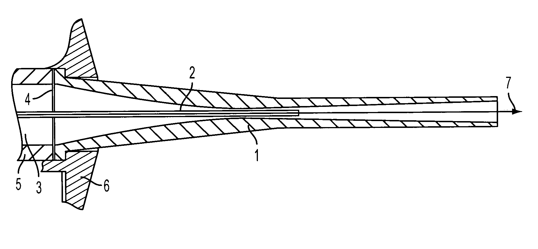
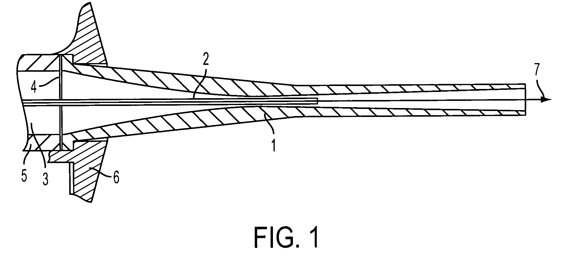
[0028]The cold gas spraying system schematically illustrated in FIG. 1 comprises a cylindrical housing 5 with an antechamber 3 situated on the inside and closed off on the output side by a gas distribution screen 4 which, in turn, is penetrated in the center by a powder (feeding) tube 2. The gas distribution screen 4 is adjoined by an outer nozzle body 1, the screen 4 and the nozzle 1 being fastened to the housing 5 by means of a union nut 6. The spraying direction of the illustrated system is indicated by an arrow 7. The powder tube 2 is axially and centrically arranged in the outer nozzle body 1. The powder tube 2, which follows the center axis of the outer nozzle body 1 and is held by the screen 4, ends, coming from the housing, behind the narrowest point in the divergent area of the outer nozzle body 1, where the gas pressure has already dropped considerably in comparison to the initial pressure and normally amounts to only half of the latter. The high initial pressure exists in...


PUM

PropertyMeasurementUnit
Areaaaaaaaaaaa
Sizeaaaaaaaaaa
Ratioaaaaaaaaaa

Abstract

A cold gas spraying method and device, whereby the sprayed particles are accelerated in a gas flow. A powder tube and an outer nozzle body together form a Laval nozzle that produces high gas flow velocities. The injection of the sprayed particles occurs in the divergent section of the Laval nozzle.

Description

CROSS REFERENCE TO RELATED APPLICATIONS[0001]This application is a continuation of international patent application no. PCT / EP02 / 04978, filed May 6, 2002, designating the United States of America, and published in German as WO 03 / 041868, the entire disclosure of which is incorporated herein by reference. Priority is claimed based on Federal Republic of Germany patent application no. DE 101 26 100.4, filed May 29, 2001.BACKGROUND AND SUMMARY OF THE INVENTION[0002]The invention relates to a method and a system for producing a coating or a structural part by means of cold gas spraying, during which powdery spraying particles are injected by means of a powder tube into a gas jet for which a gas is brought to a output pressure of up to 6.3 MPa and is expanded by way of a Laval nozzle. When the gas jet is expanded in the Laval nozzle, the spraying particles are accelerated to speeds of up to 2,000 m / sec.[0003]It is conventional to apply coatings by means of thermal spraying to many differ...

Claims


Application Information

Patent Timeline
IPC IPC(8): B05B1/00B24C5/04B05B7/04B05B7/14C23C24/04
CPCB05B7/0441B05B7/1486C23C24/04
Inventor HEINRICH, PETERSTOLTENHOFF, THORSTENRICHTER, PETERKREYE, HEINRICHRICHTER, HORST
Owner SULZER METRO AG
Why Eureka
Try Eureka