Centrifugal compressor

a centrifugal compressor and compressor technology, applied in the direction of machines/engines, stators, liquid fuel engines, etc., can solve the problems of excessive noise, achieve the effect of increasing gas flow rate, broadening stable operation range, and increasing gas flow ra

Active Publication Date: 2009-08-27
MITSUBISHI HEAVY IND LTD
View PDF2 Cites 14 Cited by
  • Summary
  • Abstract
  • Description
  • Claims
  • Application Information

AI Technical Summary

Benefits of technology

[0007]The present invention was made in light of the problems of the prior art, and the object of the invention is to provide a centrifugal compressor with which frequency of noise produced by rotation of the impeller having a plurality of blades does not resonate with natural frequency of vibration of gas in a plurality of axial slots which serve to increase gas flow rate in an operation range of increased gas flow rate and broaden stable operation range in an operation range of decreased gas flow rate resulting in reduction of noise caused by rotation of the impeller.

Problems solved by technology

However, there is a possibility that the noise produced by rotation of the impeller having a plurality of blades for compressing the gas sucked in the impeller, frequency of the noise being determined by the number of blades and rotation speed of the impeller, resonates with the vibration of gas in the slots, of which the natural frequency is determined by the length of the slot, and excessive noise is produced.

Method used


Image

  • Centrifugal compressor
  • Centrifugal compressor
  • Centrifugal compressor

Examples


first embodiment

The First Embodiment

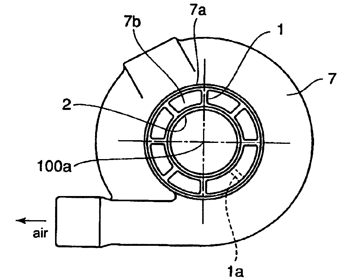
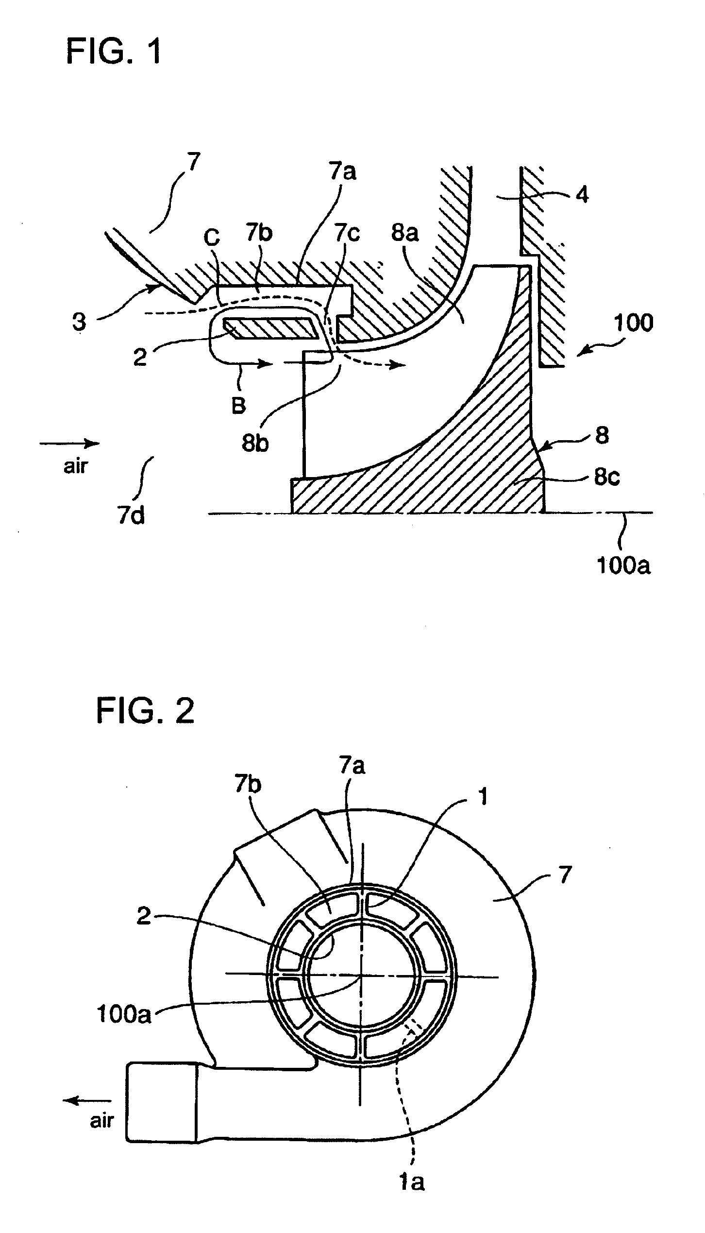
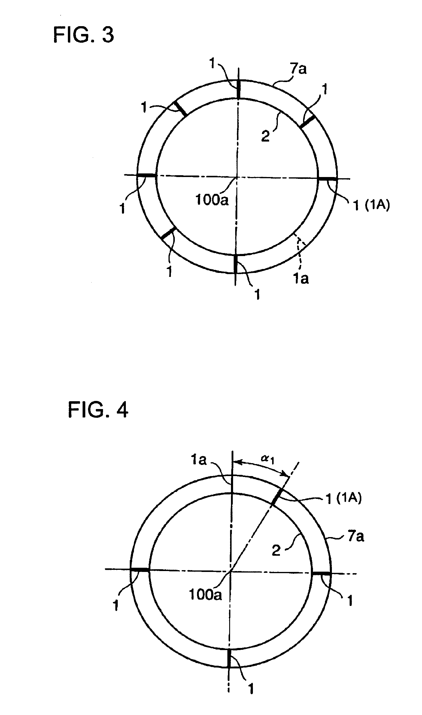
[0028]FIG. 1 is a sectional view of a substantial part of a centrifugal compressor according to the invention, and FIG. 2 is an external view of the centrifugal compressor viewed from an air inlet side. FIG. 3 is a drawing showing location of struts for partitioning slots according to the first embodiment of the invention.

[0029]Referring to FIG. 1, a centrifugal compressor 100 includes a compressor housing 7, an impeller 8 supported for rotation in the housing and a diffuser 4. The impeller 8 has a plurality of radially outwardly directed blades 8a on a hub 8c thereof, each including a leading edge, a trailing edge, and a contoured outer tip, the outer tip being free and located in close spaced relationship with a part of the inner surface of the compressor housing 7 shrouding the contoured outer tip of each blade. Reference numeral 100a indicates center of rotation of the impeller 8 and an inlet passage 7d of the housing 7.

[0030]Reference numeral 8b indicates a ...

second embodiment

The Second Embodiment

[0037]FIG. 4 is a drawing showing location of the struts for partitioning the slots according to the second embodiment.

[0038]In the second embodiment, the annular ring part 2 is supported by 4 struts, and one strut is shifted circumferentially in clockwise direction by a central angle α1 (=((180 / T)×(½-⅓))°) from a position 1a which is one of positions determined when all struts are to be provided at circumferentially equal spacing, where T is total number of struts.

[0039]Result of measurement of noise showed that, by shifting one of 4 struts circumferentially by the central angle α1 to produce unequally spaced portion of the struts, vibration exciting force components of frequency of integral multiple of the number of the struts decreased by about 50% or less as compared with the case the 4 struts was positioned at equal circumferential spacing.

third embodiment

The Third Embodiment

[0040]FIG. 5 is a drawing showing location of the struts for partitioning the slots according to the third embodiment.

[0041]In the third embodiment, the annular ring part 2 is supported by 5 or 6 struts (in the example of FIG. 5, the number of struts is 5), and one strut is shifted circumferentially in clockwise direction by a central angle α2 (=((180 / T)×(½))) from a position 1a which is one of positions determined when all 4 struts are to be provided at circumferentially equal spacing, where T is total number of struts.

[0042]Result of measurement of noise in the case of the third embodiment when the number of struts is 5 is shown in the graph of FIG. 8. By shifting one of 5 struts to produce unequally spaced portion of the struts, vibration exciting force components of frequency of integral multiple of the number of the struts decreased by about 40% or less as compared with the case the 5 struts was positioned at equal circumferential spacing. In the graph, the ...


PUM


Abstract

A centrifugal compressor can be provided with which frequency of noise produced by rotation of the impeller having a plurality of blades does not resonate with natural frequency of vibration of gas in a plurality of axial slots which serve to increase gas flow rate in an operation range of increased gas flow rate and broaden stable operation range in an operation range of decreased gas flow rate resulting in reduction of noise caused by rotation of the impeller. The axial slots are formed between the peripheral part of the inlet passage of the compressor housing by the peripheral surface of the inlet passage and an annular ring part of the housing supported by a plurality of struts extending from the peripheral surface, four or more struts are provided to support the annular ring part, and all but one of them are located at positions which will be determined when all the struts are located at circumferentially equal spacing and one of the struts is shifted circumferentially from one of said positions by a certain central angle.

Description

BACKGROUND OF THE INVENTION[0001]1. Field of the Invention[0002]The present invention relates to a centrifugal compressor for an exhaust turbo charger, etc., a compressor housing of which has an inlet passage having a diameter larger than the diameter of an annular inlet area of the impeller of the compressor, and a plurality of slots are formed in the housing near the annular inlet area of the impeller so that gas introduced from the inlet passage can be introduced into the impeller through the slots at the outer periphery of the leading edge parts of the blades in addition to gas introduced into the impeller from the annular inlet area of the impeller or gas introduced from the annular inlet area can be bleed from the impeller through the slots to the inlet passage to be again sucked into the impeller from the annular inlet area, particularly a centrifugal compressor in which said plurality of slots are arranged circumferentially concentrically with the center of rotation of the i...

Claims


Application Information

Patent Timeline
Patent Type & Authority Applications(United States)
IPC IPC(8): F04D29/42
CPCF04D29/4213F04D29/685F04D29/665F04D29/42F04D29/44
Inventor FUKAMI, KOJI
Owner MITSUBISHI HEAVY IND LTD
Why Eureka
Try Eureka