Thermal Power Plant Exhaust Purification Device

Active Publication Date: 2017-10-26
DEMIST TECH +1
View PDF0 Cites 10 Cited by
  • Summary
  • Abstract
  • Description
  • Claims
  • Application Information

AI Technical Summary

Benefits of technology

[0038]1. The cooling substance flows in the cooling substance flow channel, such that the condensate precipitated from the hot exhaust uniformly adheres on the exhaust contact surface, and thus forming a uniform and stable water film; on one hand, the formation of the concentrated H2SO4 on a dust collecting plate is prevented, and a liquid film flows downwards under gravity, thereby cleaning the H2SO4 adhered on the dust collecting plate timely; on the other hand, the water film is really effective in intercepting droplets and capturing the dust.
[0039]2. The electrostatic demisting and dedusting technology, the liquid film demisting and dedusting technology and the traditional corrugated plate curved channel demisting technology are dynamically integrated, which greatly increases the efficiency of intercepting and separating the dust and droplets.
[0040]3. The uniform and stable water film can effectively prevent the phenomenon of back corona.
[0041]4. The water-saving effect. Not only extra rinsing water is not necessary, but also the condensate is collected from the

Problems solved by technology

By practical application and comparison, the two types of wet electrostatic precipitators have the following disadvantages in that: 1. the water flow is not distributed uniformly during drip washing, so a uniform water film cannot be formed, which causes a dry-wet interface to be formed on the anode plate, and the dust collecting plate/collecting tube is short in service life; 2. there is only one electrostatic measurement for intercepting dust and droplets; 3. an gas flow rate allowed is relatively low, and is about 1˜3 m/s,

Method used


Image

  • Thermal Power Plant Exhaust Purification Device
  • Thermal Power Plant Exhaust Purification Device
  • Thermal Power Plant Exhaust Purification Device

Examples


first embodiment

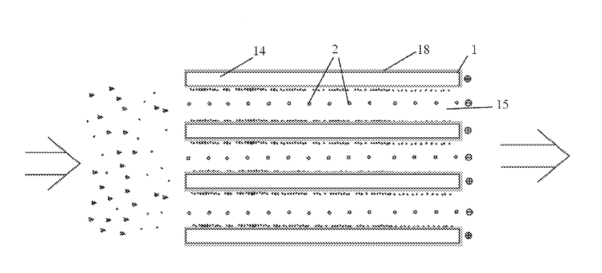
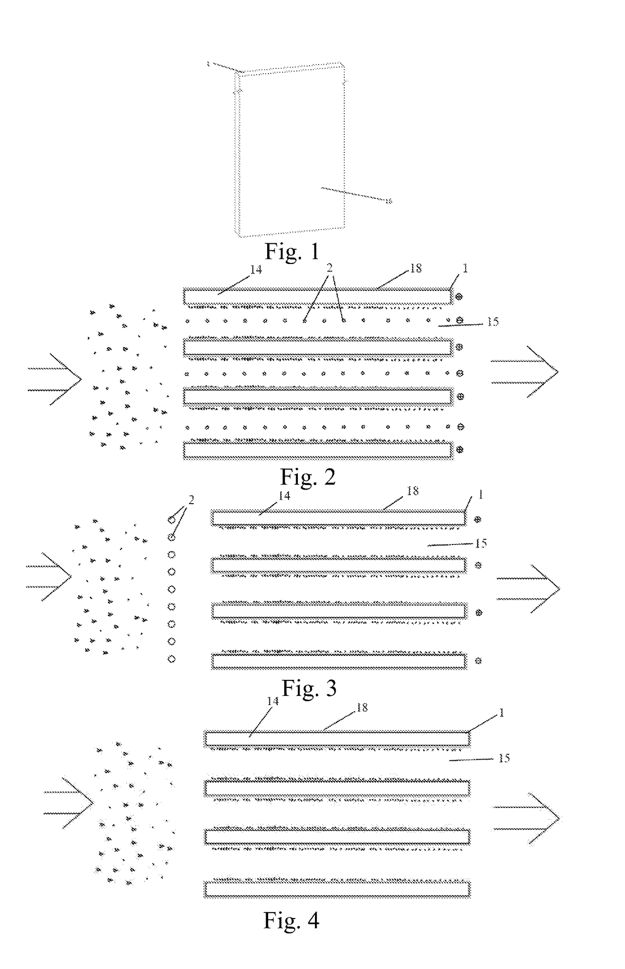
[0065]FIGS. 1-2 show one embodiment of the present invention. It can be seen from the drawings that the thermal power plant exhaust purification device mainly includes a hollow plate 1, a cooling substance flow channel 14 and an exhaust flow channel 15, and the hollow plate 1 has an exhaust contact surface 16 for collecting dust and / or mist contained in the exhaust.

[0066]In the present embodiment, the thermal power plant exhaust purification device is provided with a plurality of hollow plates 1 which are arranged in parallel at intervals. The distance between the two adjacent hollow plates 1 is about 300 mm. The cooling substance flow channel 14 is defined by the hollow structure of the hollow plate 1, and the exhaust flow channel 15 is defined by the two adjacent hollow plates 1; a cooling substance flow inlet is communicated with a water supply system, and a cooling substance flow outlet is communicated with a water discharge system; the cooling substance flow inlet and the flow ...

second embodiment

[0070]FIG. 1 and FIG. 3 show another embodiment of the present invention. It can be seen from the drawings that the thermal power plant exhaust purification device mainly includes a hollow plate 1, a cooling substance flow channel 14 and an exhaust flow channel 15, in which the hollow plate 1 has an exhaust contact surface 16 for collecting dust and / or mist contained in the exhaust.

[0071]In the present embodiment, the thermal power plant exhaust purification device is provided with a plurality of hollow plates 1 which are arranged in parallel at intervals. The distance between the two adjacent hollow plates 1 is about 300 mm. The cooling substance flow channel 14 is defined by the hollow structure of the hollow plate 1, and the exhaust flow channel 15 is defined by the two adjacent hollow plates 1; a cooling substance flow inlet is communicated with a water supply system, and a cooling substance flow outlet is communicated with a water discharge system; the cooling substance flow in...

third embodiment

[0075]FIG. 1 and FIG. 4 show another embodiment of the present invention. It can be seen from the drawings that the thermal power plant exhaust purification device mainly includes a hollow plate 1, a cooling substance flow channel 14 and an exhaust flow channel 15, in which the hollow plate 1 has an exhaust contact surface 16 for collecting dust and / or mist contained in the exhaust.

[0076]In the present embodiment, the thermal power plant exhaust purification device is provided with a plurality of hollow plates 1 which are arranged in parallel at intervals. The distance between the two adjacent hollow plates 1 is about 40 mm. The cooling substance flow channel 14 is defined by the hollow structure of the hollow plate 1, and the exhaust flow channel 15 is defined by the two adjacent hollow plates 1; a cooling substance flow inlet is communicated with a water supply system, and a cooling substance flow outlet is communicated with a water discharge system; the cooling substance flow inl...


PUM

PropertyMeasurementUnit
Temperatureaaaaaaaaaa
Distanceaaaaaaaaaa
Distanceaaaaaaaaaa

Abstract

A thermal power plant exhaust purification device, the device including a cooling substance flow channel and an exhaust flow channel; the device also includes a spacing member for spacing and exchanging heat between the cooling substance flow channel and the exhaust flow channel, the spacing member having an exhaust contact surface for collecting dust and/or mist contained in the exhaust; the cooling substance flows in the cooling substance flow channel, such that the condensate precipitated from hot exhaust uniformly adheres on the exhaust contact surface, thus forming a uniform and stable water film; on one hand, formation of the concentrated H2SO4 on a dust collecting plate is prevented, and a liquid film flows downwards under gravity, thereby cleaning the H2SO4 adhered on the dust collecting plate timely; on the other hand, the water film is very effective in intercepting droplets and capturing the dust.

Description

FIELD OF THE INVENTION[0001]The present invention relates to the field of air purification, and in particular, to a thermal power plant exhaust purification device.DESCRIPTION OF THE PRIOR ART[0002]In the prior art, an effective thermal power plant exhaust purification device is generally a wet electrostatic precipitator, the dust collection process of which includes three processes of charging, collecting and cleaning dust and droplets. Therefore, correspondingly, a complete wet electrostatic precipitator includes a dust and droplets charging system, a collecting system and a cleaning system. A metal discharge wire in the wet electrostatic precipitator ionizes its ambient gas under a DC high voltage, such that the surface of a dust droplet particle is charged. Charged particles move toward a dust collection polar plate under an electric field force, and deposit thereon. Traditionally, in most cases, a spray water flow is adopted, which flows down from a top end of a dust collecting...

Claims


Application Information

Patent Timeline
IPC IPC(8): B01D53/74B01D46/02F23J15/00B01D46/00B01D53/34
CPCB01D53/74F23J15/00B01D46/00B01D53/34B01D46/02F23J15/06F23J2219/70B01D45/08B01D53/002B01D53/323B03C3/08B03C3/12B03C3/16B03C3/41B03C3/47B01D2257/302B01D2257/80B01D2258/0283B03C2201/04Y02E20/30
Inventor CHENG, ZIJIANWENG, GUOKU
Owner DEMIST TECH
Why Eureka
Try Eureka