Low-pressure drop structure of particle adsorbent bed for adsorption gas separation process
a gas separation and low-pressure drop technology, applied in the direction of separation processes, dispersed particle separation, chemistry apparatus and processes, etc., can solve the problems of large, limited mass transfer rate achievable, large residence time, etc., to optimize thermal mass/heat, optimize heat transfer structure, and reduce the effect of gas flow pressure drop
- Summary
- Abstract
- Description
- Claims
- Application Information
AI Technical Summary
Benefits of technology
Problems solved by technology
Method used
Image
Examples
example 1
Working Example of the Present Invention in the Form of a Rectangular Stack
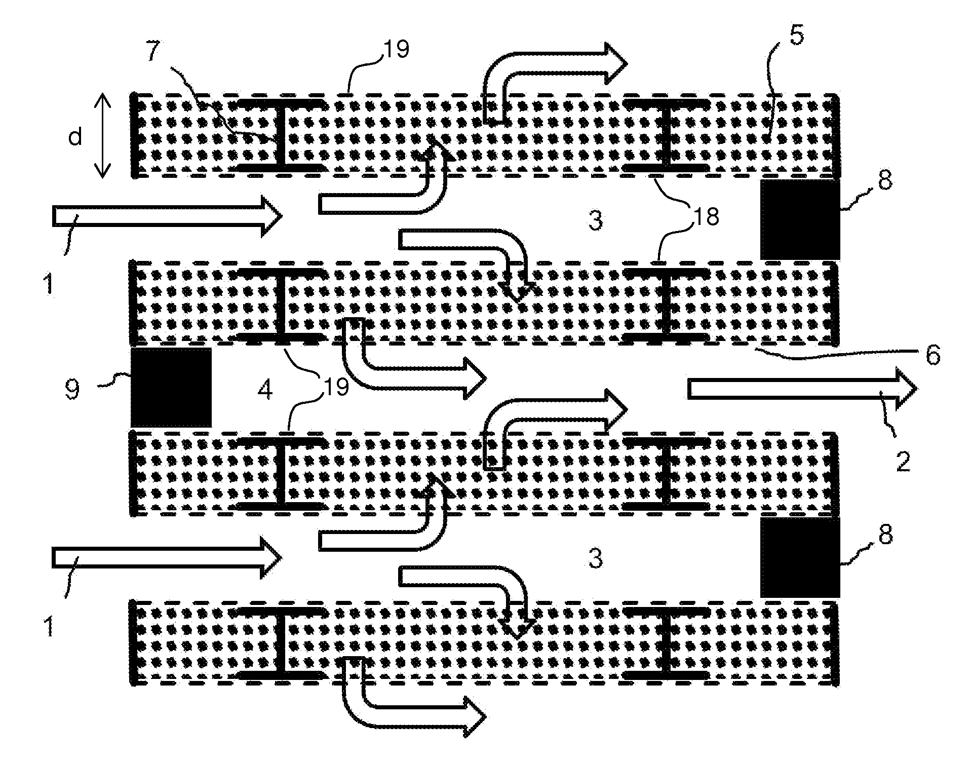
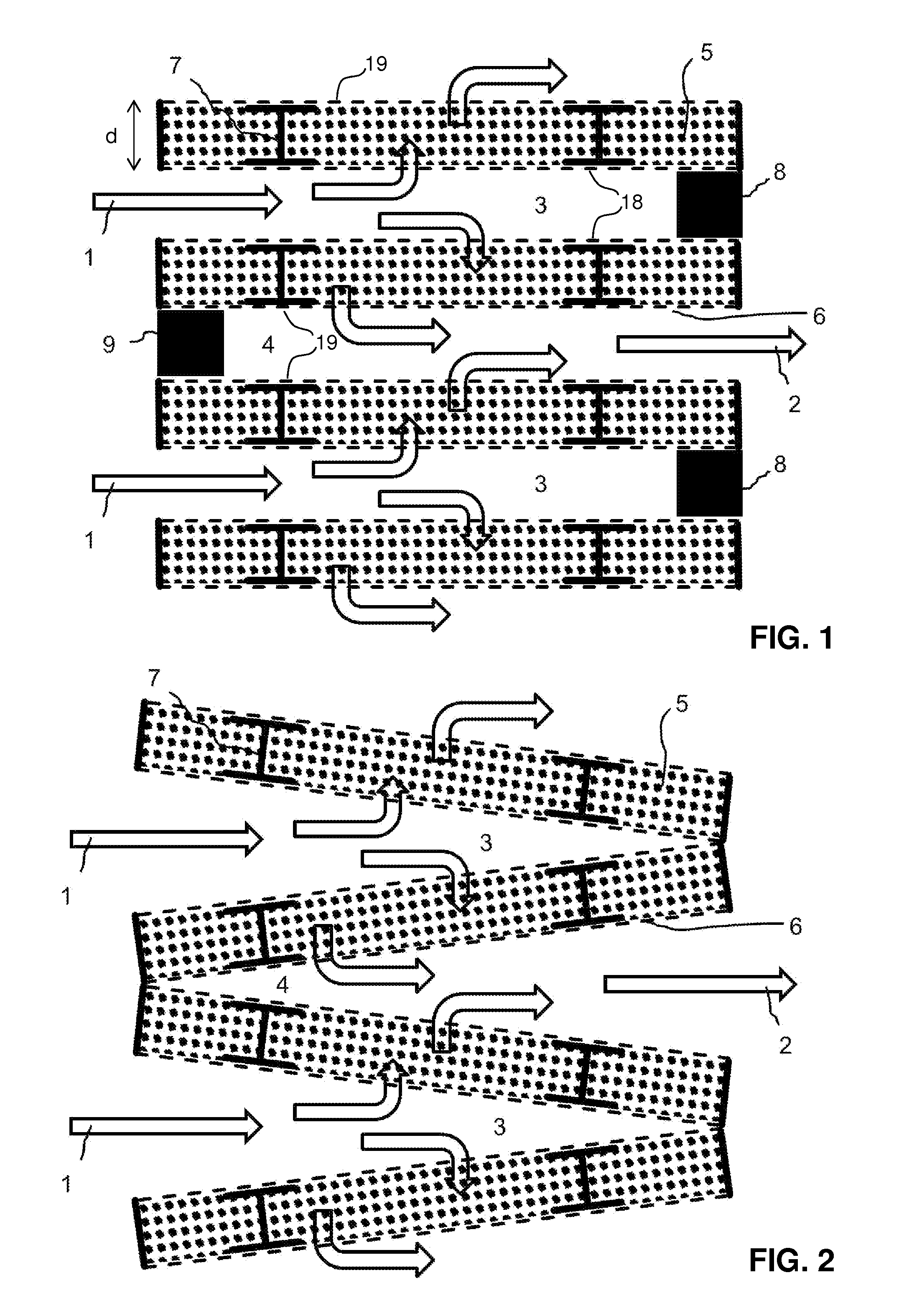
[0101]According to one working example, the structure is composed of rectangular layers of sorbent material stacked on top of each other to form a rectangular block shaped stack comprising inlet channels, outlet channels and the sorbent layers. In this example, the fabrication and assembly of this example is described to illustrate the applicability of this invention in the form of a useful product for CO2 extraction from ambient air.
[0102]The individual sorbent material layers are formed by stiff frame structures, each comprising a rectangular frame with 0.5 m×0.6 m edge length and a height of 1 cm, made of stainless steel profiles. A top-view of such a single frame is shown in FIG. 10, a respective cross section in FIG. 11. The fabrication and assembly of the overall structure comprises the following steps:[0103]1. The frame structures are fabricated by welding stainless steel profiles (e.g. for high-volume...
example 2
Determination of the Pressure Drop Through a Stack of Sorbent Layers
[0122]The pressure drop imposed on an air flow passing through a structure essentially fabricated according to the description of Example 1 is experimentally determined for different flow rates. To this end, both butterfly valves are opened and a variable speed fan is attached to the inlet opening producing different air flow rates through the stack. The flow rate is measured with an in-pipe velocity head meter and the pressure drop over the structure is measured using a differential pressure sensor. The observed pressure drop for various volume flow rates is shown in the following table:
Volume flow (m3 / h)Pressure drop (Pa)20016400316005880098
[0123]It is found that up to the design flow rate of 800 m3 / h, which is required to capture around 1 kg of CO2 from air per cycle (see Example 3), the pressure drop stays below 100 Pa. If the average pressure drop during the adsorption process is 100 Pa, the required pumping wo...
example 3
Performance of Example 1 within a Cyclic Adsorption / Desorption Process
[0125]A structure essentially fabricated according to the description of Example 1 is used for a cyclic temperature-vacuum swing adsorption / desorption process to extract CO2 from ambient air. One cycle of the process takes about 6 hours and comprises the steps adsorption (3 hours) and desorption (3 hours).
[0126]During the adsorption step, according to Example 2 above, the butterfly valves are opened and air is blown through the structure by a variable speed fan, while the flow rate is recorded. Further, the CO2 content of the air flow and its relative humidity are measured before and after the vacuum chamber using an infrared detector. The relative humidity during the adsorption process is relatively constant between 35% and 40%. The air flow is 750 to 800 m3 / h. The CO2 concentration before and after the chamber (“adsorption breakthrough curves”) during adsorption are shown in FIG. 10.
[0127]It is surprisingly foun...
PUM
| Property | Measurement | Unit |
|---|---|---|
| relative inclination angles | aaaaa | aaaaa |
| relative inclination angles | aaaaa | aaaaa |
| particle diameter | aaaaa | aaaaa |
Abstract
Description
Claims
Application Information
 - R&D
- Intellectual Property
- Life Sciences
- Materials
- Tech Scout
- Unparalleled Data Quality
- Higher Quality Content
- 60% Fewer Hallucinations
Browse by: Latest US Patents, China's latest patents, Technical Efficacy Thesaurus, Application Domain, Technology Topic, Popular Technical Reports.
© 2025 PatSnap. All rights reserved.Legal|Privacy policy|Modern Slavery Act Transparency Statement|Sitemap|About US| Contact US: help@patsnap.com


