Personal protective suit with partial flow restriction

a technology of flow restriction and protective suit, which is applied in chemical protection, nuclear engineering, nuclear elements, etc., can solve the problems of difficult to meet regulatory requirements of protective suits made without faces, relatively expensive assembly of face pieces, and high cost of protective suits, so as to reduce measured co2 levels and reduce carbon dioxide levels.

Inactive Publication Date: 2005-09-27
3M INNOVATIVE PROPERTIES CO
View PDF75 Cites 21 Cited by
  • Summary
  • Abstract
  • Description
  • Claims
  • Application Information

AI Technical Summary

Benefits of technology

[0014]a partial flow restriction between the hood portion and body portion that can permit gasses to pass from the hood portion to the body portion while reducing carbon dioxide levels in front of the wearer's mouth.
[0015]The invention permits fabrication of a protective suit that can provide a comfort-enhancing airstream and reduced measured CO2 levels without employing a face piece.

Problems solved by technology

In addition, face piece assemblies also relatively expensive to manufacture and can add substantially to the overall cost of a protective suit.
It can be difficult to meet regulatory requirements in suits made without a face piece but embodying the above-described comfort-enhancing airstream.
We have found that air that freely passes from the head portion of the suit to a non-return valve located below the wearer's neck tends not to carry with it a sufficient quantity of CO2 exhaled by the wearer.

Method used


Image

  • Personal protective suit with partial flow restriction
  • Personal protective suit with partial flow restriction
  • Personal protective suit with partial flow restriction

Examples


Embodiment Construction

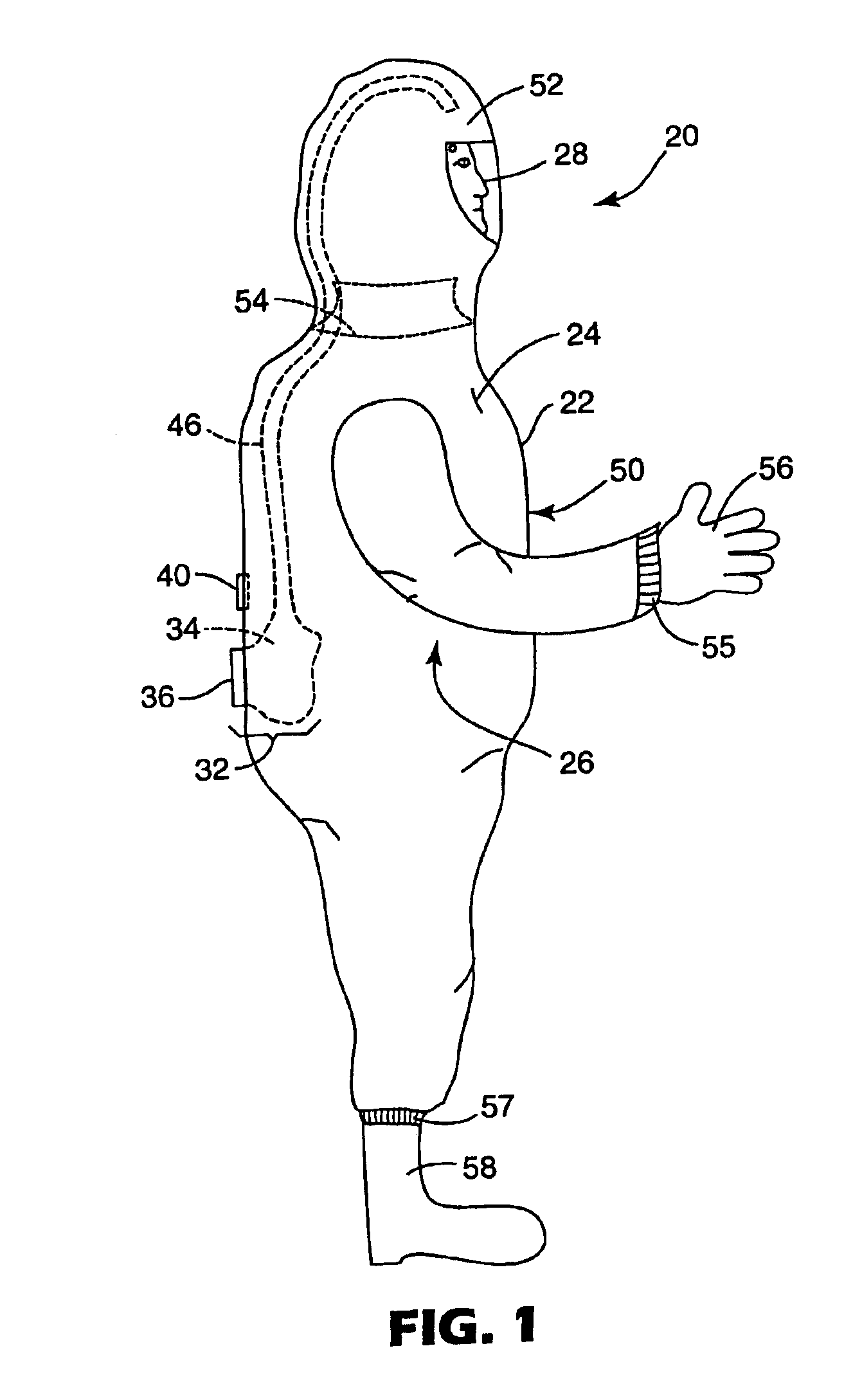
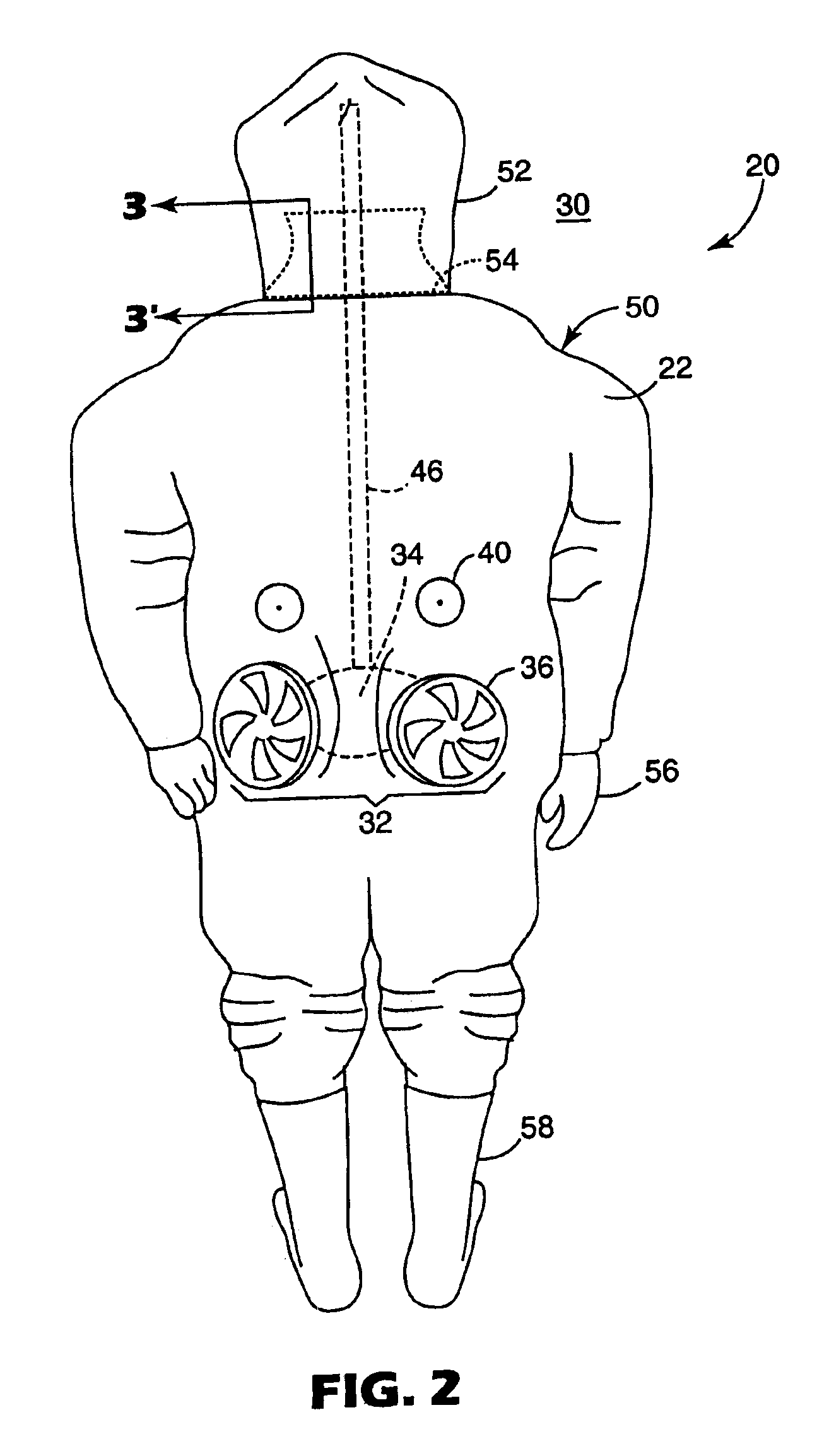
[0020]The personal protective suits of the invention can be any of a variety of protection systems that preferably surround or otherwise encase or encapsulate the wearer and may be suitable for protecting living things from a contaminated or hazardous environment. For example, the suit can be a fully enveloping protective garment such as a chemical suit or a hooded casualty bag. The suit can also be a partially protective garment such as a smoke hood and tunic. Still other examples, both known and unknown, are intended to fall within the scope of this invention. The inner environment of the personal protective suit is intended to be habitable and contaminant-free when worn in a contaminated or hazardous outer environment.

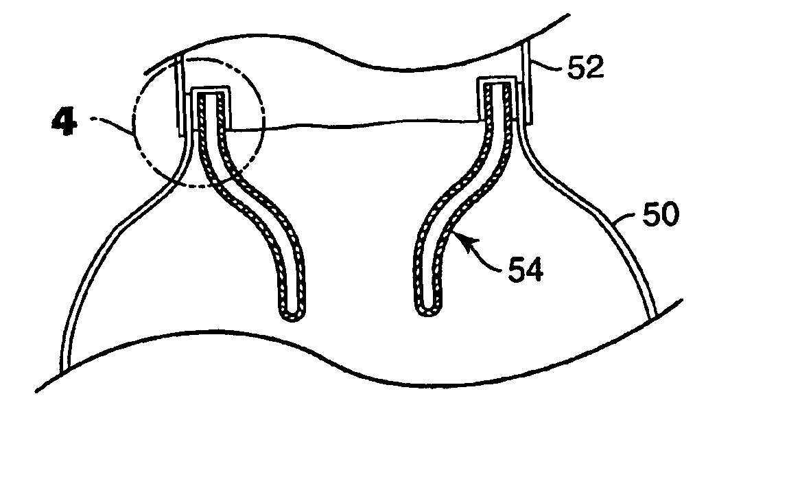
[0021]FIG. 1 shows a schematic side view and FIG. 2 shows a rear view of an example, or embodiment, of personal protective suit 20 constructed in accordance with the present disclosure. Suit 20 includes a body portion 50 that generally envelops the torso 24 of weare...


PUM


Abstract

A personal protective suit for a wearer includes a hood portion located generally above the wearer's neck and at least partially enveloping the wearer's nose and mouth, a body portion located generally below the wearer's neck and at least partially enveloping the wearer's torso, an air delivery system that can deliver air to the hood portion, a vent that can permit gasses to escape from the body portion, and a partial flow restriction between the hood portion and body portion of the suit. The partial flow restriction permits gasses to pass from the hood portion to the body portion while reducing carbon dioxide levels in front of the wearer's mouth. The suit can be fabricated without requiring a face piece.

Description

CROSS-REFERENCE TO RELATED APPLICATION[0001]This application is a continuation-in-part of application Ser. No. 10 / 121,306 filed Apr. 12, 2002, now abandoned entitled PERSONAL CONTAINMENT SYSTEM WITH ISOLATED BLOWER, the entire disclosure of which is incorporated herein by reference.[0002]This invention relates to protective suits adapted to a wearer or user from a contaminated environment. This invention also relates to protective suits having ah air delivery system.BACKGROUND[0003]Personal containment systems can protect a user from a variety of harmful chemical or biological agents. Many examples of personal containment systems that can surround a user are known, such as protective suits, protective tents, casualty bags for injured persons, and the like. These systems preferably isolate the user's entire body from contaminants. Often, the contaminants include respiratory hazards, and the systems must employ air delivery systems so that the user is able to breathe when isolated fro...

Claims


Application Information

Patent Timeline
Patent Type & Authority Patents(United States)
IPC IPC(8): A62B17/00A62B18/04A62B18/00
CPCA62B17/006A62B18/045Y10S2/906
Inventor AVERY, MARTIN J.ODELL, RAYMONDGRAVES, JASON A.
Owner 3M INNOVATIVE PROPERTIES CO
Why Eureka
Try Eureka