Transient voltage clamping circuit

a transient voltage and clamping circuit technology, applied in the direction of electric variable regulation, emergency protective arrangements for limiting excess voltage/current, instruments, etc., can solve the problems of increasing the cost of hdd, increasing the voltage in the power supply, and destroying the asic, so as to achieve accurate activation and low cost , the effect of low activation threshold

Inactive Publication Date: 2009-05-12
STMICROELECTRONICS ASIA PACIFIC PTE
View PDF21 Cites 22 Cited by
  • Summary
  • Abstract
  • Description
  • Claims
  • Application Information

AI Technical Summary

Benefits of technology

[0013]Advantageously, embodiments of the transient voltage clamping circuit of the invention provide accurate activation, low cost and low tolerance in activation threshold voltage relative to the prior art.

Problems solved by technology

Under certain conditions, inductive loads may dump their stored energy (in the form of large currents) on the power supply of the ASIC causing the voltage in the power supply to rise.
As a result, the drain voltage of the high side drivers may rise to levels which cause the destruction of the ASIC.
1. A transient voltage suppressor (TVS) can be used externally to the ASIC to clamp the voltage. This increases the cost of the HDD and the voltage tolerance of the TVS is often wide, which can lead to inadequate suppression of transient voltages. For example, if the required TVS operating range is 13.2V (i.e., 12V supply +10%) to 16V (the absolute rating) and TVS voltage tolerance is wide, it may not be able to effectively clamp in the required range.
2. An alternative is to put a very large capacitor on the ASIC power supply to absorb the dumped energy. However, such large capacitors are costly.
3. A simple voltage clamp circuit consisting of zener-npn or zener-nmos devices can also be used to absorb the dumped energy. Such a circuit can be integrated into the ASIC or may be external. However, the wide tolerance of activation voltage and long response time makes this circuit unsuitable for use in applications where the operating voltage range and the absolute maximum voltage of the ASIC are relatively close to each other. HDDs of small dimension require lower tolerances in activation voltage than are provided by these circuits.

Method used


Image

  • Transient voltage clamping circuit
  • Transient voltage clamping circuit
  • Transient voltage clamping circuit

Examples


Embodiment Construction

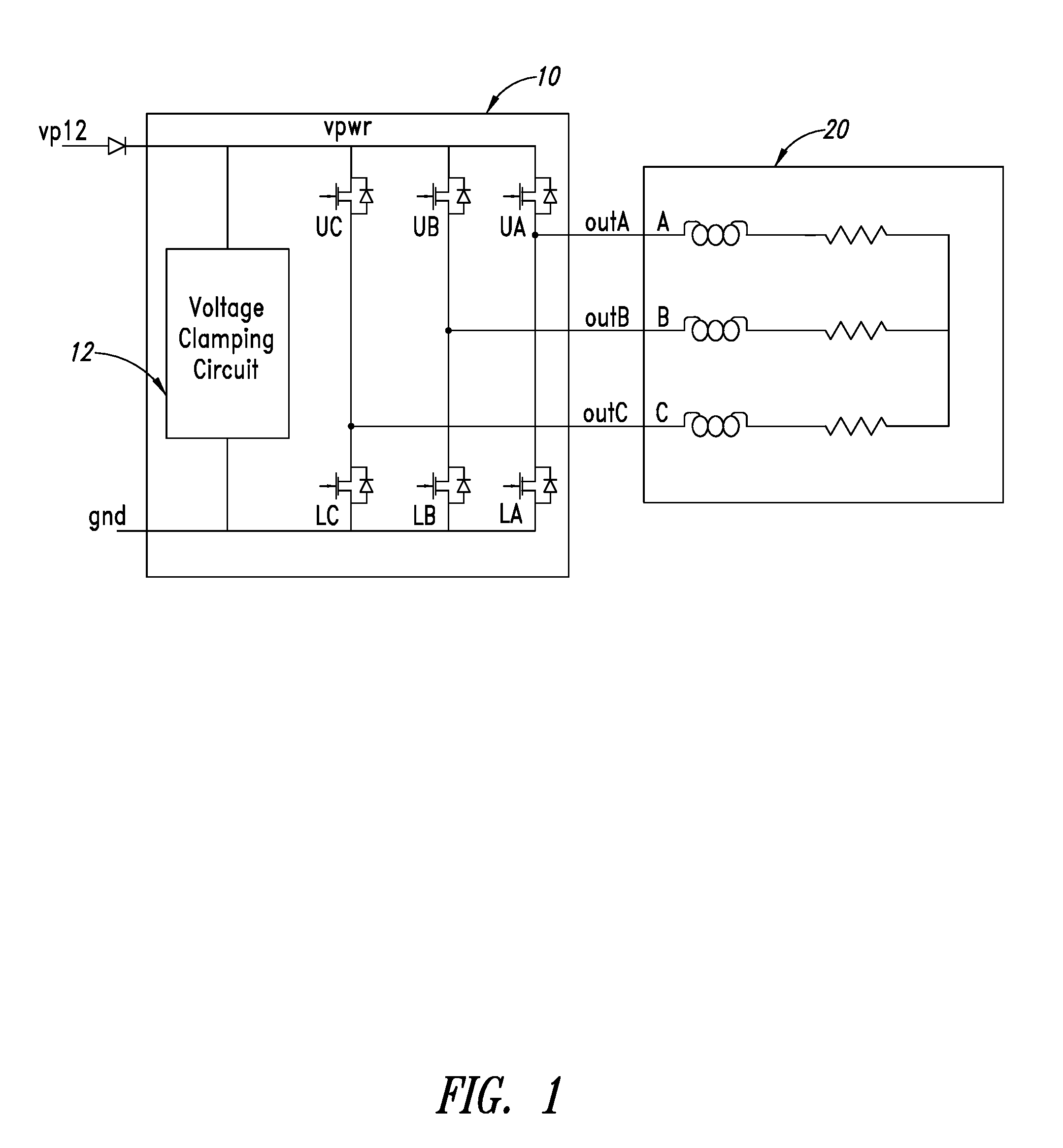
[0019]Referring to FIG. 1, a hard disk drive (not shown) includes a motor 20 which receives power through a power ASIC 10. The motor 20 receives power on lines A, B, C from power ASIC 10, each of those lines having an impedance model which includes inductive and resistive impedances. UA, UB and UC are gate drive signals for upper power DMOS transistors for each line A, B and C. LA, LB and LC are for corresponding lower power DMOS transistors. These DMOS transistors provide current to the motor 20.

[0020]Power ASIC 10 receives power from an external 12 volt power supply VP12. Power ASIC 10 includes a voltage clamping circuit 12 for clamping transient voltages which are dumped from the inductive loads in the motor 20 and is powered from the power supply rail of the power ASIC 10. The duty cycle of the dumped current is generally small (typically in the order of 3%) and therefore the location of the clamping circuit on the power ASIC 10 does not pose a power dissipation problem if an ap...


PUM


Abstract

A circuit for transient voltage clamping, the circuit being internal to a motor driver ASIC for a hard drive and including a power transistor for sinking a power supply voltage subjected to transient variation, a reference circuit for deriving a first reference voltage from a second reference voltage and the power supply voltage, and an amplifier circuit for receiving the first reference voltage as input and for driving the power transistor.

Description

BACKGROUND OF THE INVENTION[0001]1. Field of the Invention[0002]The present invention relates to a circuit for transient voltage clamping and, in particular, a circuit for transient voltage clamping within an ASIC that is a motor driver for a disk drive.[0003]2. Description of the Related Art[0004]In typical hard disk drive (HDD) applications, specific integrated circuits (ASICs) are used for driving the spindle and voice coil motors. Under certain conditions, inductive loads may dump their stored energy (in the form of large currents) on the power supply of the ASIC causing the voltage in the power supply to rise. Reverse isolation blocking diodes are usually provided to prevent the system power supply from absorbing the excess energy. As a result, the drain voltage of the high side drivers may rise to levels which cause the destruction of the ASIC. Therefore a voltage clamp is required to be placed on the supply voltage of the ASIC for reducing the effects of such transient voltag...

Claims


Application Information

Patent Timeline
Patent Type & Authority Patents(United States)
IPC IPC(8): H02H3/22H02H9/00H02H7/122H02H9/04
CPCH02H9/041H02H7/1227
Inventor RANA, LEGAL REPRESENTATIVE, SWARNALIRANA, SAKTI PADA
Owner STMICROELECTRONICS ASIA PACIFIC PTE
Why Eureka
Try Eureka