Electrically driven linear actuator

A linear actuator and electric drive technology, applied in the direction of electric components, electromechanical devices, electrical components, etc., can solve the problems of distorted target moving distance, distorted results, fatigue of elastic intermediate members, etc., and achieve high reliability and operational safety , the effect of high actuation precision

Inactive Publication Date: 2007-11-14
BOSCH REXROTH AG
View PDF3 Cites 9 Cited by
  • Summary
  • Abstract
  • Description
  • Claims
  • Application Information

AI Technical Summary

Problems solved by technology

[0009] 1) Even after relatively short operations, the elastic intermediate member will fatigue, which will distort the expected target movement distance
[0010] 2) It is difficult to adjust the damping characteristics of the intermediate member for any operating condition, so as not to dampen the vibration that will be generated by the object while still suppressing the vibration (usually high frequency)
[0011] 3) The elastic intermediate member is exposed to the respective environmental conditions, and it is generally difficult to find a material with sufficient temperature strength in the range of -21 to 70°C, and at the same time has sufficient resistance to oil or solvent
[0012] 4) The intermediate member deforms elastically not only in the actuation direction, but also in the transverse direction relative to the actuation direction; however, the deformation in the actuation direction can be compensated by the corresponding actuation sequence control measurement in the spindle drive control , while the deformation in the other direction is difficult to compensate, thus distorting the simulation results

Method used


Image

  • Electrically driven linear actuator
  • Electrically driven linear actuator

Examples


Embodiment Construction

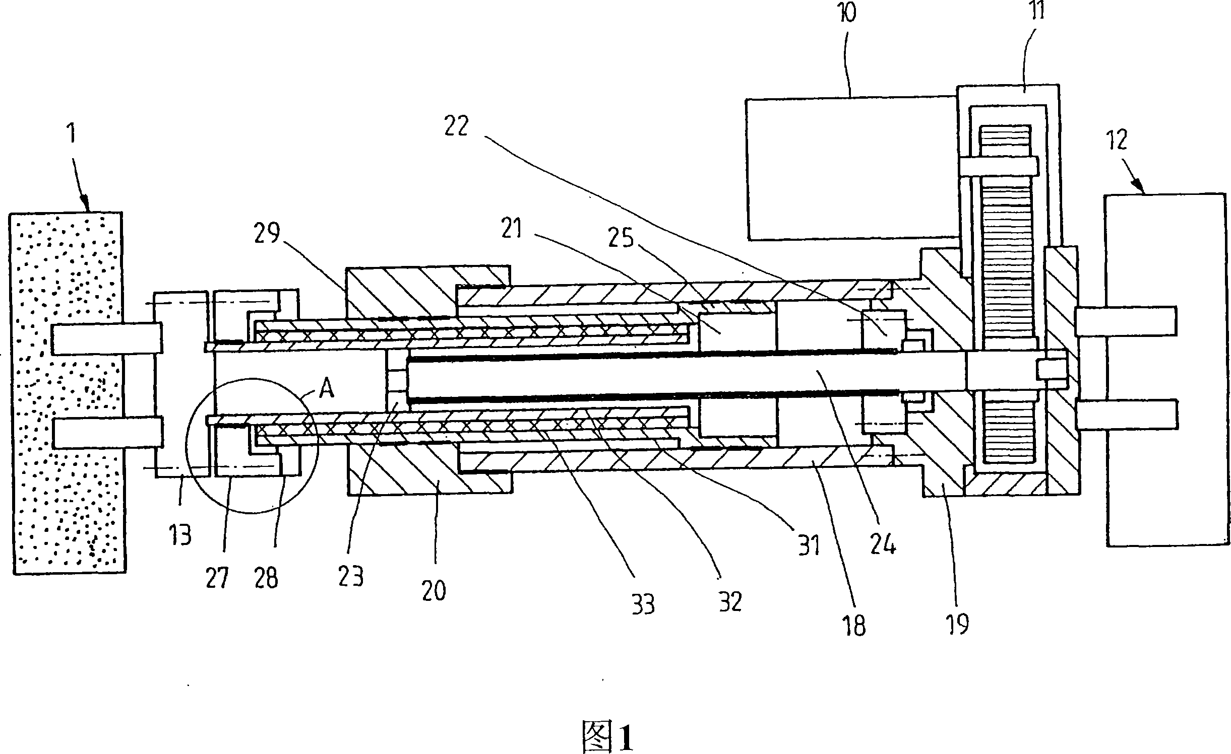
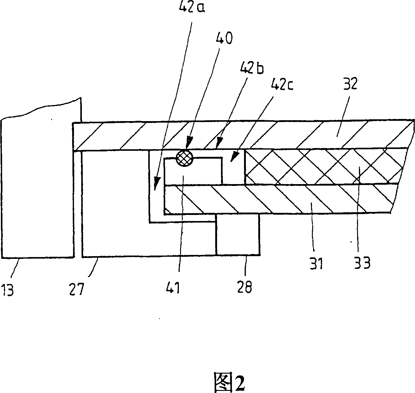
[0027] As shown in Figure 1, the linear actuator of the present invention comprises a sleeve 18, which has a sleeve bottom 19 disposed at one end thereof, and a sleeve head 20 disposed at its other end; transmission 11 to the casing bottom 19; and an electric motor 10 for driving by the transmission 11; a spindle 24 mounted coaxially inside the casing 18 and through a transmission-side bearing 22 And the output side bearing 23 is installed in a rotatable manner. A spindle nut 21 engaged with the external thread of the spindle 24 is inserted on the spindle 24 . The spindle nut 21 is held inside a piston 25 mounted to slide on the inner surface of the sleeve 18 and is coupled via the piston 25 to an outer cylinder or actuator tube 31 which communicates with an inner cylinder or actuator tube 31 . The actuator tube 32 and the elastic material layer 33 frictionally connecting the two actuator tubes 31 and 32 together form a hollow cylindrical actuator element. The outer actuator...


PUM


Abstract

The present invention relates to a power factor correction circuit for compensating distortion of an input current. According to the exemplary embodiment of the present invention, a turn-on interval length of a switch is controlled according to a voltage induced in a secondary winding wire of an inductor since the voltage induced in the secondary winding wire has information on an input voltage when the switch is turned on. The turn-on interval length of the switch is reduced when the input voltage is great and is increased when the input voltage is low. Therefore, distortion of the input current may be compensated by controlling the turn-on interval of the switch according to the voltage induced in the secondary winding wire without using an additional circuit for sensing the input voltage.

Description

technical field [0001] The invention relates to an electrically driven linear actuator according to the preamble of claim 1 . Background technique [0002] Electrically driven linear actuators of a general type are used to reciprocate a specific object (mass) in a linear direction, enabling substantially more precise actuation while simplifying control, for example, compared to hydraulically driven linear actuators. Furthermore, there is no risk of contamination due to leaking hydraulic oil. [0003] Previously known electrically driven linear actuators (see, for example US 6,145,395 or US 4,712,441 ) act on the object to be actuated by means of a tubular actuator element, wherein the tubular actuator is connected by suitable means on the output side Frictionally coupled to an object. The tubular actuator element is mounted so as to slide axially within a main pipe (usually used as a housing) and is coupled on the input side to a spindle nut which is then inserted onto the...

Claims


Application Information

Patent Timeline
Patent Type & Authority Applications(China)
IPC IPC(8): F16H25/20B25J9/12F16H57/00
CPCY10T74/18712F16H57/0006H02K7/06Y10T74/18656Y10T74/18576Y10T74/18664F16H25/20
Inventor 莱奥·莫科
Owner BOSCH REXROTH AG
Why Eureka
Try Eureka