
Heat insulation wall and energy-saving heat insulation house

A technology for thermal insulation of walls and walls, applied in thermal insulation, walls, roofs, etc., can solve problems such as unutilized solar heat energy, poor wall strength and durability, and poor wall insulation performance, so as to enhance resistance to natural disasters The ability to steal and rob, simplify the design and construction process, and shorten the construction period

Inactive Publication Date: 2011-08-17
吕云于
View PDF6 Cites 10 Cited by
  • Summary
  • Abstract
  • Description
  • Claims
  • Application Information

AI Technical Summary

Problems solved by technology

[0003] In order to solve the problems of complex construction process, long construction period, poor wall insulation performance, poor wall strength and durability, and unutilized solar heat energy received by the roof, the present invention proposes a thermal insulation wall and energy-saving and heat-insulating houses, the technical solutions adopted are:

Method used


Image

  • Heat insulation wall and energy-saving heat insulation house
  • Heat insulation wall and energy-saving heat insulation house
  • Heat insulation wall and energy-saving heat insulation house

Examples


Embodiment Construction

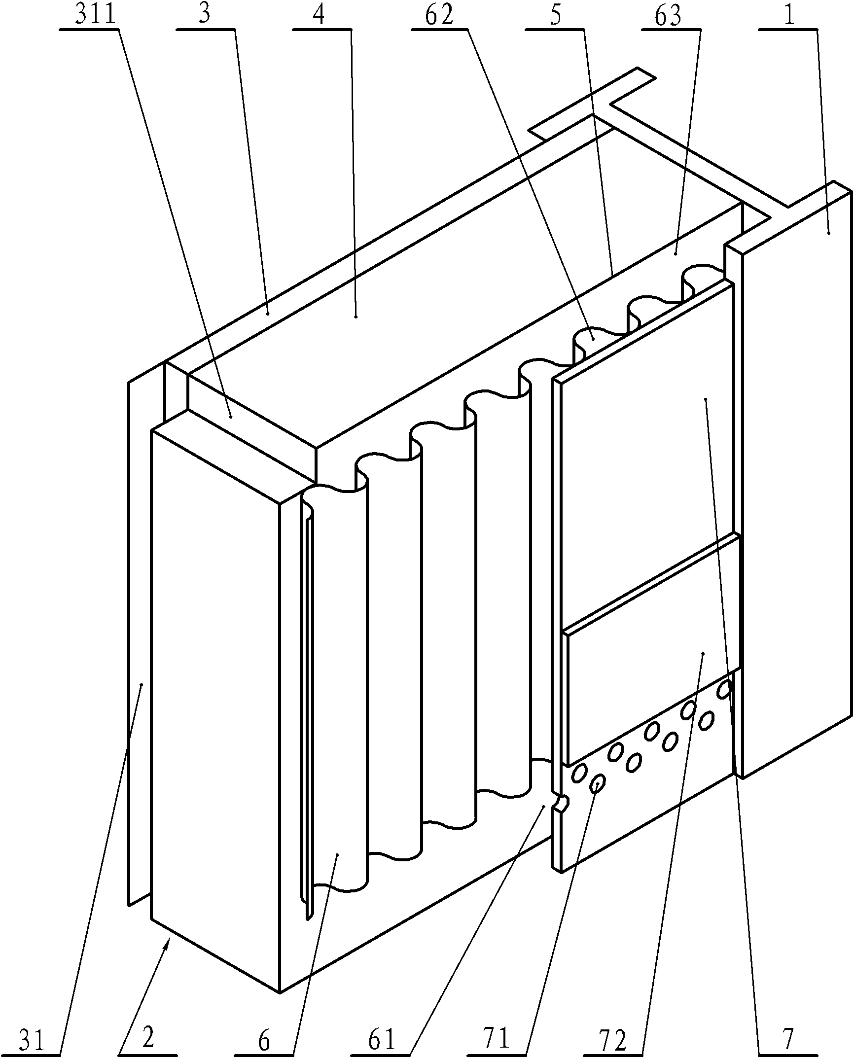
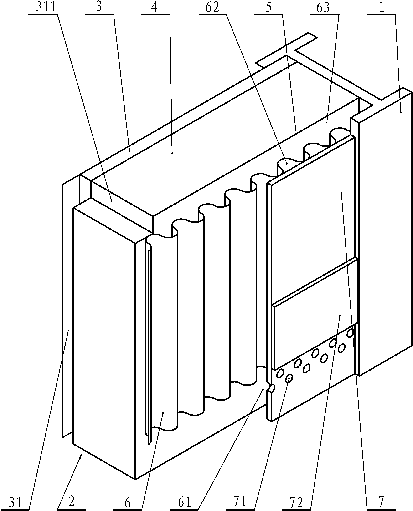
[0030] The thermal insulation wall of the present invention is composed of multi-layer structure joints, and the structure is as attached figure 1 As shown, it includes wall inner panels 3, thermal insulation layers 4, thin iron sheet layers 5, corrugated iron sheet layers 6, and thick iron sheet layers 7 arranged from indoor to outdoor along the thickness direction of the thermal insulation wall body 2. The multi-layer structure is compact. The height of the corrugated iron plate layer 6 is less than the height of the thermal insulation wall 2, the lower edge of the corrugated iron plate layer 6 is higher than the lower edge of the thermal insulation wall 2, and an air inlet channel communicating with the outside is set between the lower edge of the thermal insulation wall 61. The upper edge of the corrugated iron plate layer 6 is lower than the upper edge of the thermal insulation wall, and between the upper edge of the thermal insulation wall and the upper edge of the extern...


PUM

PropertyMeasurementUnit
Plate thicknessaaaaaaaaaa

Abstract

The invention discloses a heat insulation wall. A wall inner plate, a heat insulation layer, a thin iron plate layer, a corrugated iron plate layer and a thick iron plate layer are arranged from the interior of the house to the exterior of the house sequentially; all layers are fixedly connected with each other; an air inlet channel and an air outlet channel are formed between the lower side of the corrugated iron plate layer and the exterior of the house, and between the upper side of the corrugated iron plate layer and the exterior of the house respectively; convex-concave grooves of the corrugated iron plate layer are communicated with the air inlet channel and the air outlet channel; and a plurality of through air holes are formed on the part of the thick iron plate layer adjacent to the air inlet channel. In an energy-saving heat insulation house, a roof frame consists of profile steel; a solar water heater is arranged on a roof; a heat collector of the solar water heater is used as a roof tile of a sunny slope or is arranged below and close to the roof tile of the sunny slope; the shape and the size of a water tank adapt to the inner outline of a ridge; and the water tank is positioned in the ridge. The heat insulation wall has the high heat insulation and ventilation performance, and the heat collector of the solar water heater is used as the roof tile of the sunny slope or is arranged below and close to the roof tile of the sunny slope so that the solar energy heat absorbed by the roof can be fully utilized.

Description

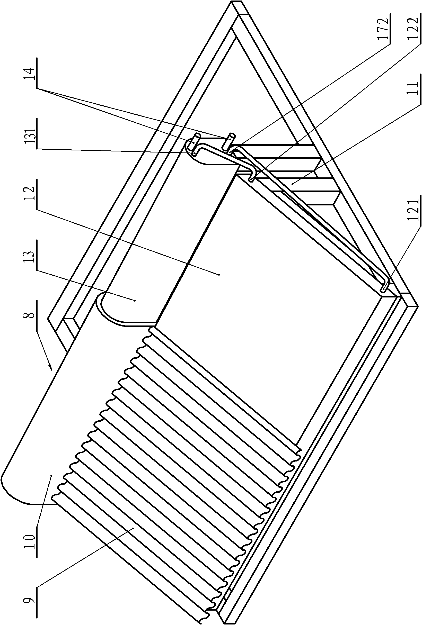
technical field [0001] The invention relates to a wall body, in particular to a thermal insulation wall body and an energy-saving thermal insulation house. Background technique [0002] As the earth's resources are decreasing day by day, the content of greenhouse gases in the atmosphere is increasing and the trend of climate warming is becoming more and more obvious. The construction process of thermal insulation houses is complicated, the construction period is long, the insulation performance of the walls is not good, the strength and durability of the walls are poor, and they are easily damaged in strong storms or encountering robbery. The popularization and application of energy-saving and thermal insulation houses. Contents of the invention [0003] In order to solve the problems of complex construction process, long construction period, poor wall insulation performance, poor wall strength and durability, and unutilized solar heat energy received by the roof, the pre...

Claims


Application Information

Patent Timeline
IPC IPC(8): E04B2/00E04B1/76E04F17/04E04F13/00E04B7/00E04D13/18F24J2/46F24J2/52
CPCY02B10/20Y02E10/47
Inventor 吕云于
Owner 吕云于
Learn More